Prologue
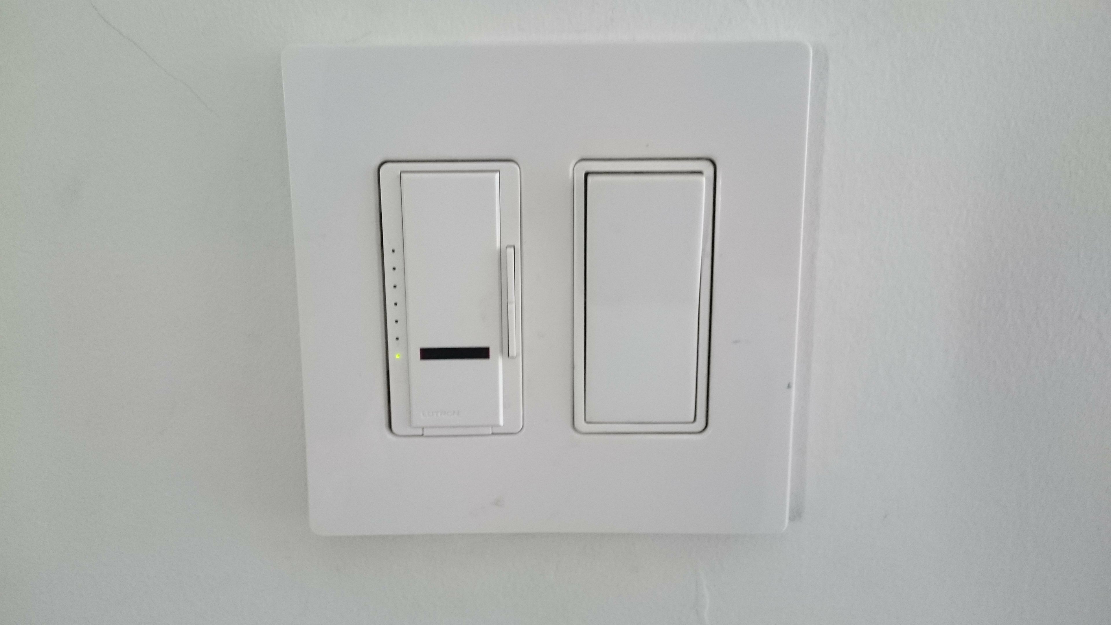
I recently moved in a new apartment in which the living room lights could be controlled with a remote. Having already played with IR signals in order to incorporate remote control to some of my projects I knew that I would probably be able to emulate the signals sent by the original remote and thus operate the lights of my living room from a web based application.

My first reflex was to think of using an Arduino with a wifi/ethernet shield. I could have used the ever usefull aRest library in order to build a REST api on the microcontroller. The web-app would have been hosted on a remote server and used as an graphical interface in order to make the right calls to the Arduino.
But this time I wanted to take a less low-level approach and it was a perfect opportunity to get my hands on a raspberry pi. With its computing and networking capabilities plus a direct control over the GPIO pins, the pi allows me to run the web-server and manage the IR signals from the same device. Furthermore I can use packages that will make my life so much easier, and use the full potential of the Pi to create a very complete hub for my domotics needs.
What we will be making
The idea is to make a web application that will allow us to easily control our home appliances. The project is based around the Raspberry pi which is used to :
- Record and store the IR signal of the remotes we wish to emulate.
- Play back the signals in memory.
- Host a web-app working as an interface with the IR module.
Additionally, we’ll see how we can leverage the capabilities of the pi in order to add more functionalities to our application.
The whole project relies on the Open Source Universal Remote created by Alex Bain.
Table of contents
- Part 1 : Handling IR signals : Hardware.
- Part 2 : Handling IR signals : Software.
- Part 3 : Setting up a web-application with NodeJs.
- Part 4 : Additional functionalities.
Handling the IR signals : Hardware
Components list
- 1x Raspberry Pi
- 2x 940 nm IR LEDs
- 1x P2N2222 transistor
- 1x 22 ohms resistor
- 1x 10k ohms resistor
- 1x TSOP38238 38KHz IR receiver
- 5x female to male jumper wires – for breadboard circuit
- 1x breadboard
- 1x protoboard
- 1x box header
- 1x GPIO Ribbon cable
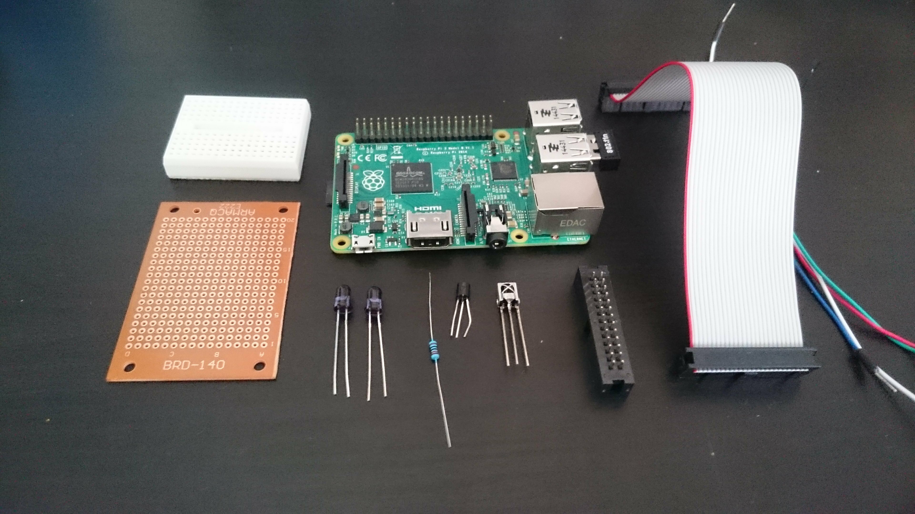
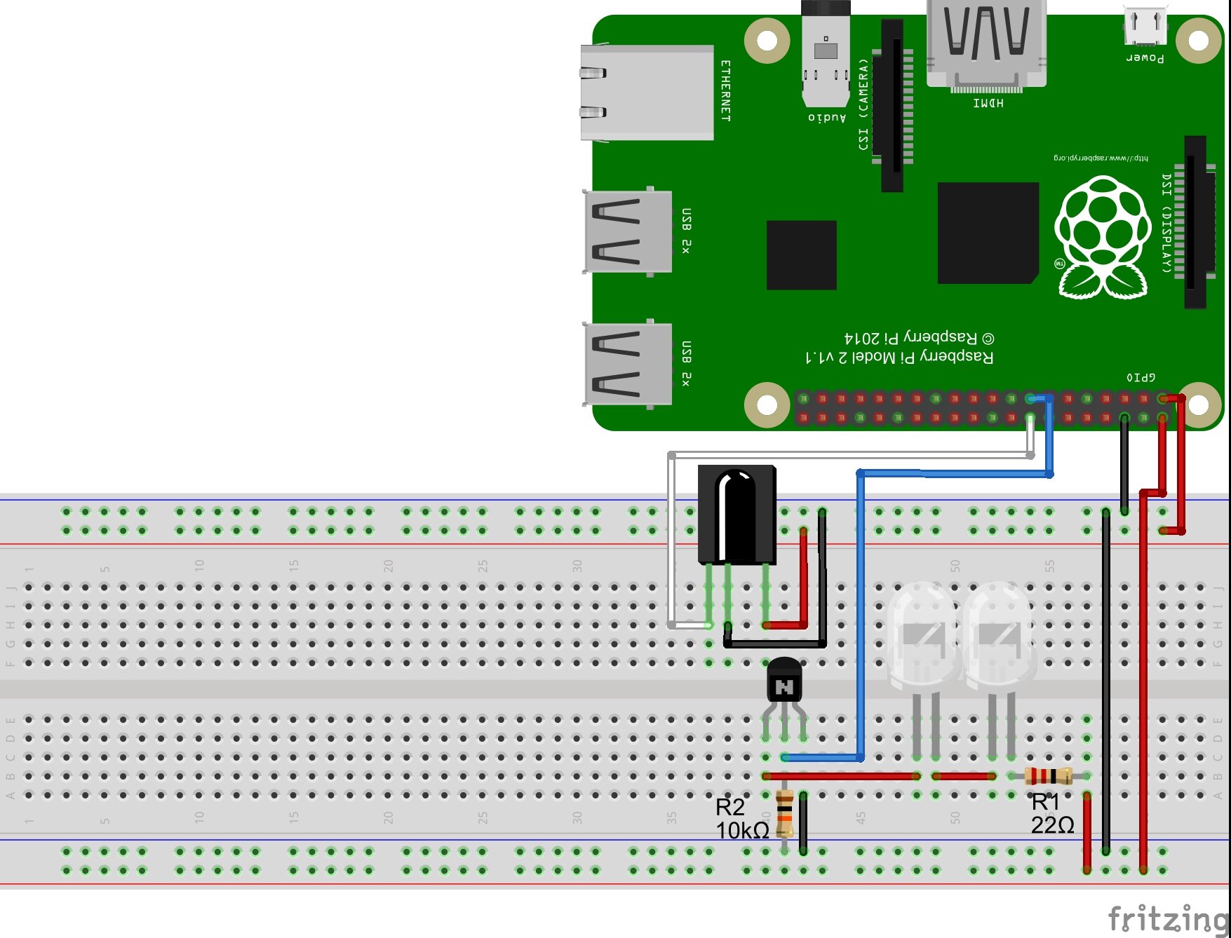
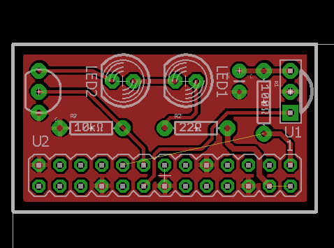
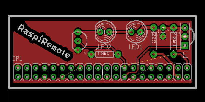
Note 1 : You might notice that a resistor is missing from this picture and the next depicting the circuit on breadboard. It’s because I included it later on after I received additional advice on the circuit. So the missing resistor should be there. In case of doubt, trust the schematic, not the pictures.
Note 2 : choose the GPIO ribbon cable and the header according to your version of the Pi. Version 1 uses 2×13 pins, version 2 uses 2×20. Or you can use a 2×13 on a rsp2 like I did so that some gpio pins stay accessible directly on the pi, but you might have to modify the header of the cable a little bit (scratch a bit of plastic on the side so that it can plug in correctly).
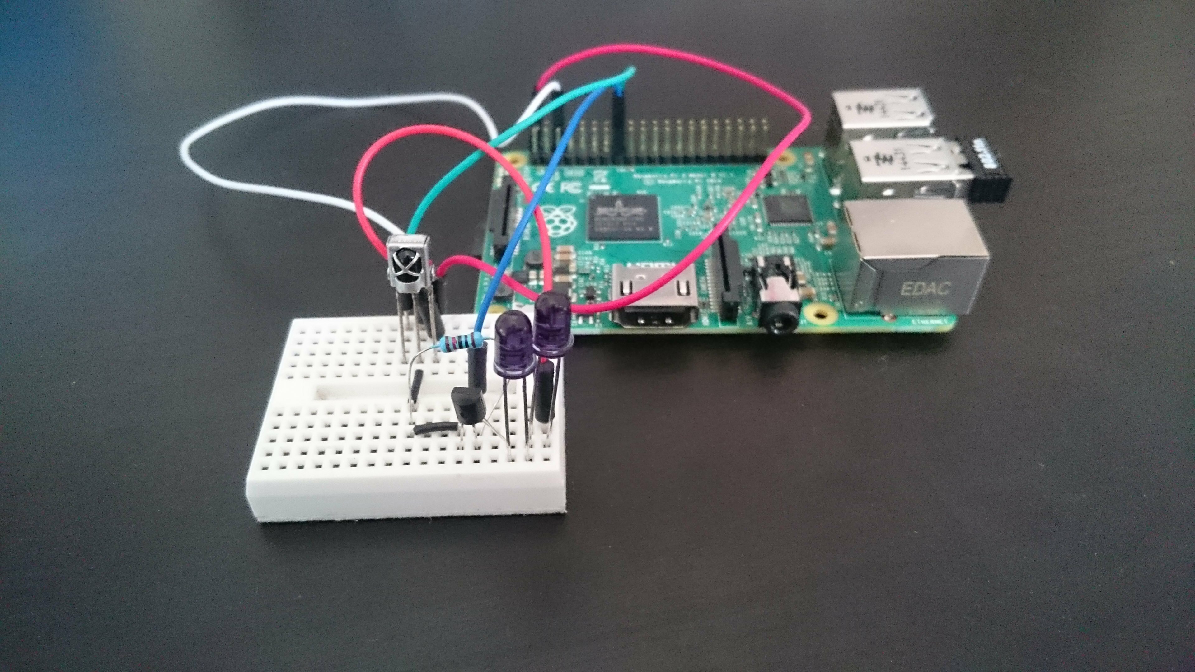
Making the circuit
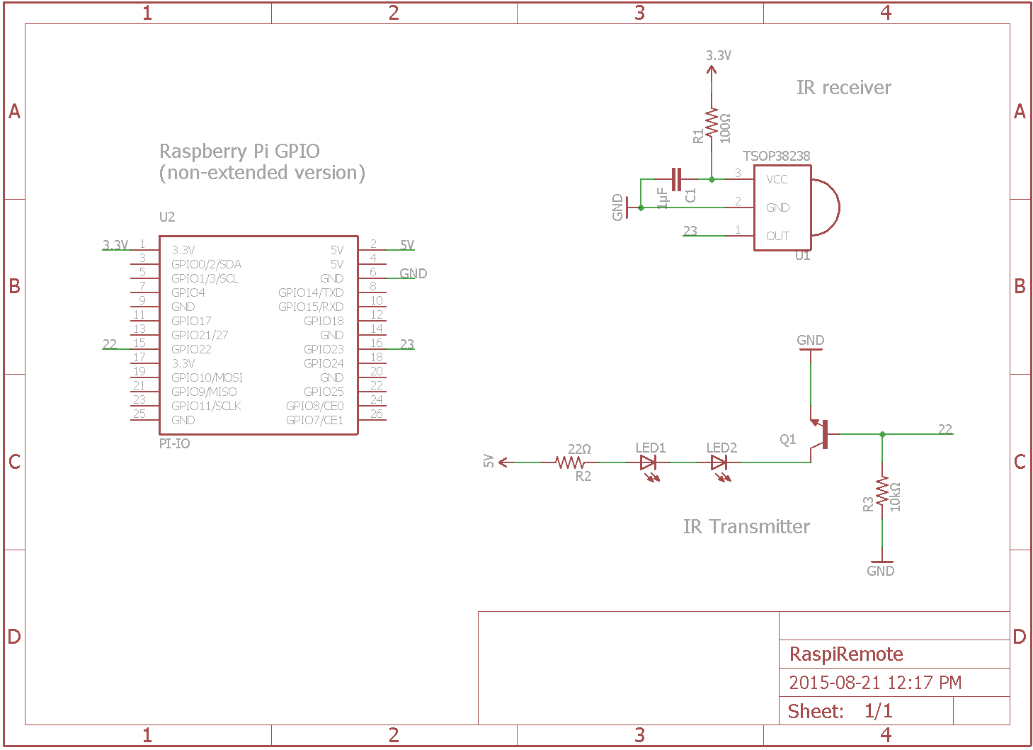
We are going to start by testing everything on a breadboard to make sure that the components work properly. It is a rather simple circuit : the IR sensor is powered up by the 3.3v pin and the output goes to one of the GPIO pins. A NPN transistor controlled by another GPIO pin is used to switch the LEDs on and off. We can’t connect the LEDs directly to one of the GPIO pins because the current provided wouldn’t be enough. Finally two resistors are used, one to limit the current coming in to the base of the transistor and the other to protect the LEDs.
Note : how can you find the proper value for the resistor R1 ? Using Ohm’s law of course ! The formula is R=V/I. Here V is the total voltage available minus the consumption of the two LEDs and the transistor. These informations can be found on the datasheets of your components. For the transistor, look for the voltage drop which is indicated by the collector-emitter saturation voltage VCE(sat). For the LEDs, you’ll be looking for the forward voltage V(f) and the forward current I(f). The formula thus becomes R = (Vsource – VCE(sat)-V(f)*2)/I(f). Here Vsource = 5, VCE(sat)=0.6, V(f)=1.7 and I(f)=0.01 (100mA). So R=(5-0.6-1.7*2)/0.01 = 100ohms. But since IR LEDs commonly have I(f)=50 instead of 100 we’ll use a 22ohms in order to accommodate a wider range of components.
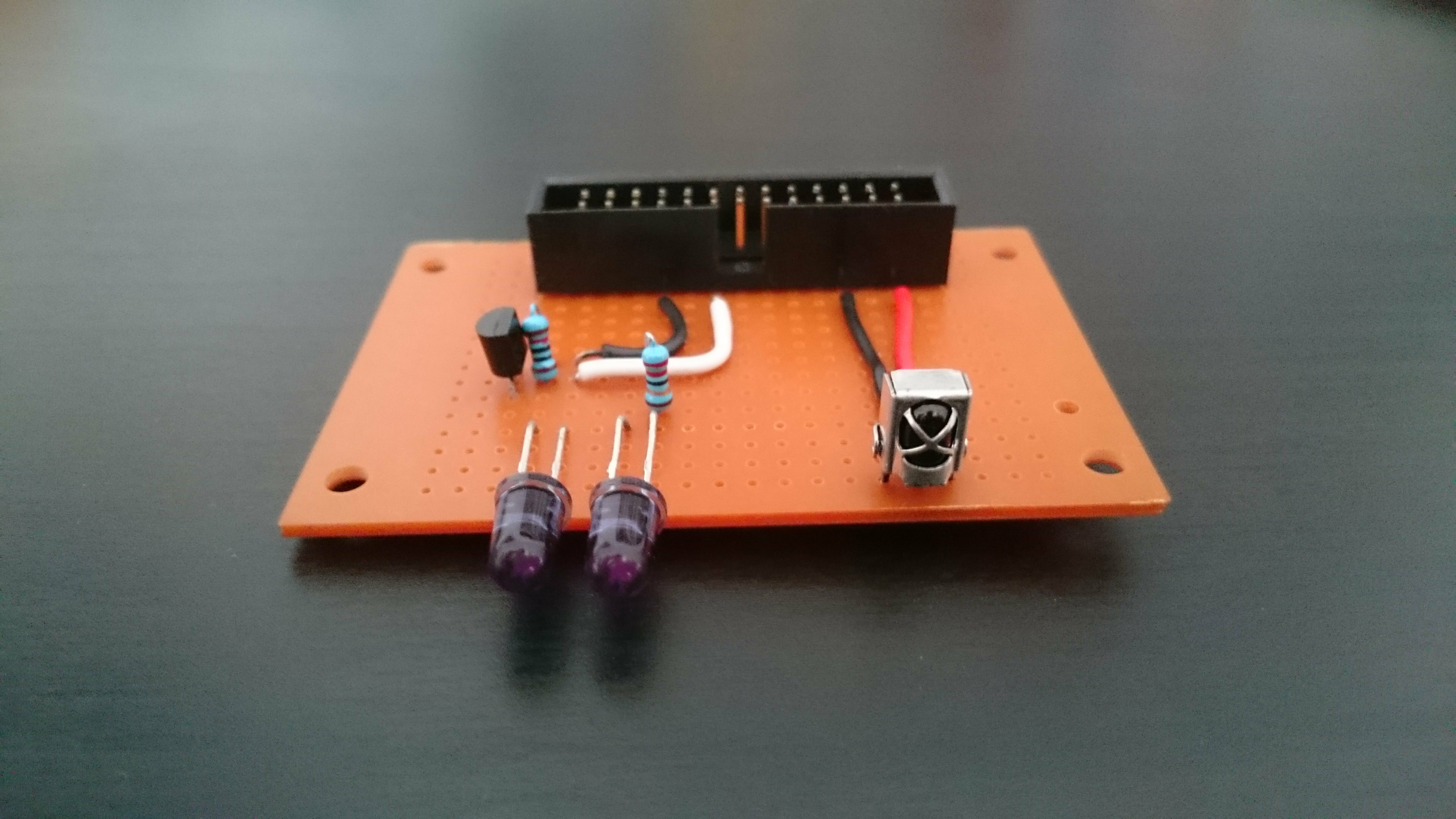
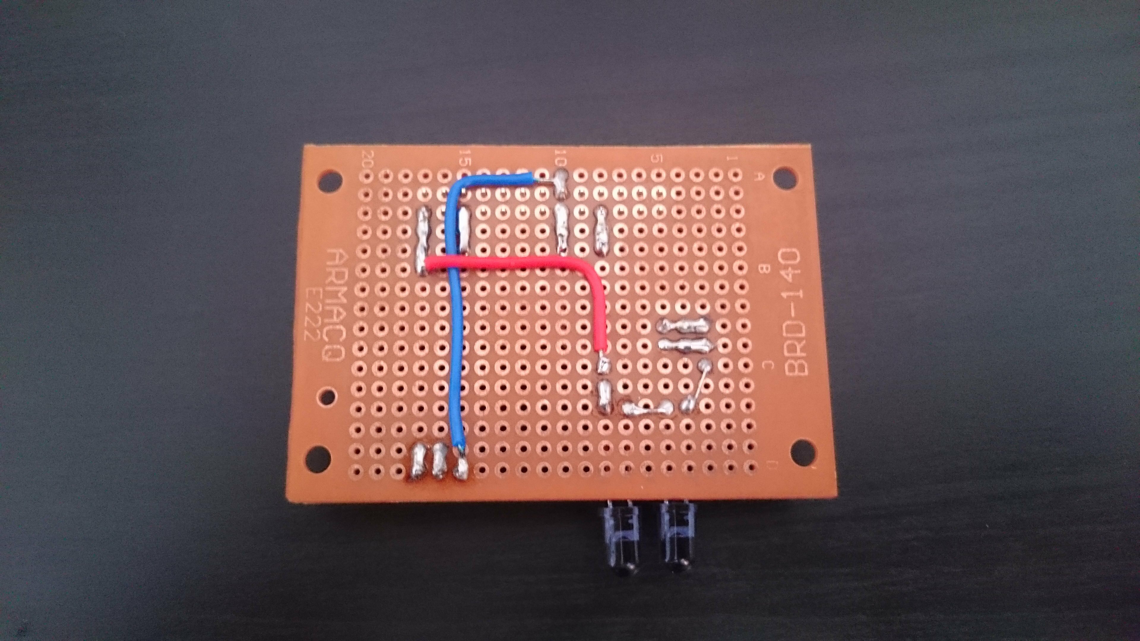
Now is the time to warm up the soldering iron. In the following schematic you’ll notice two new components R1 and C1. These are optional. The datasheet of the IR receiver advises to include them in order to protect the circuit against electrostatic perturbations. We’re here to learn about good practices aren’t we ? I thus added them to the schematic, but the circuit would work without it. In fact, you’ll see that I didn’t include them myself in the protoboard version but did in the PCB.
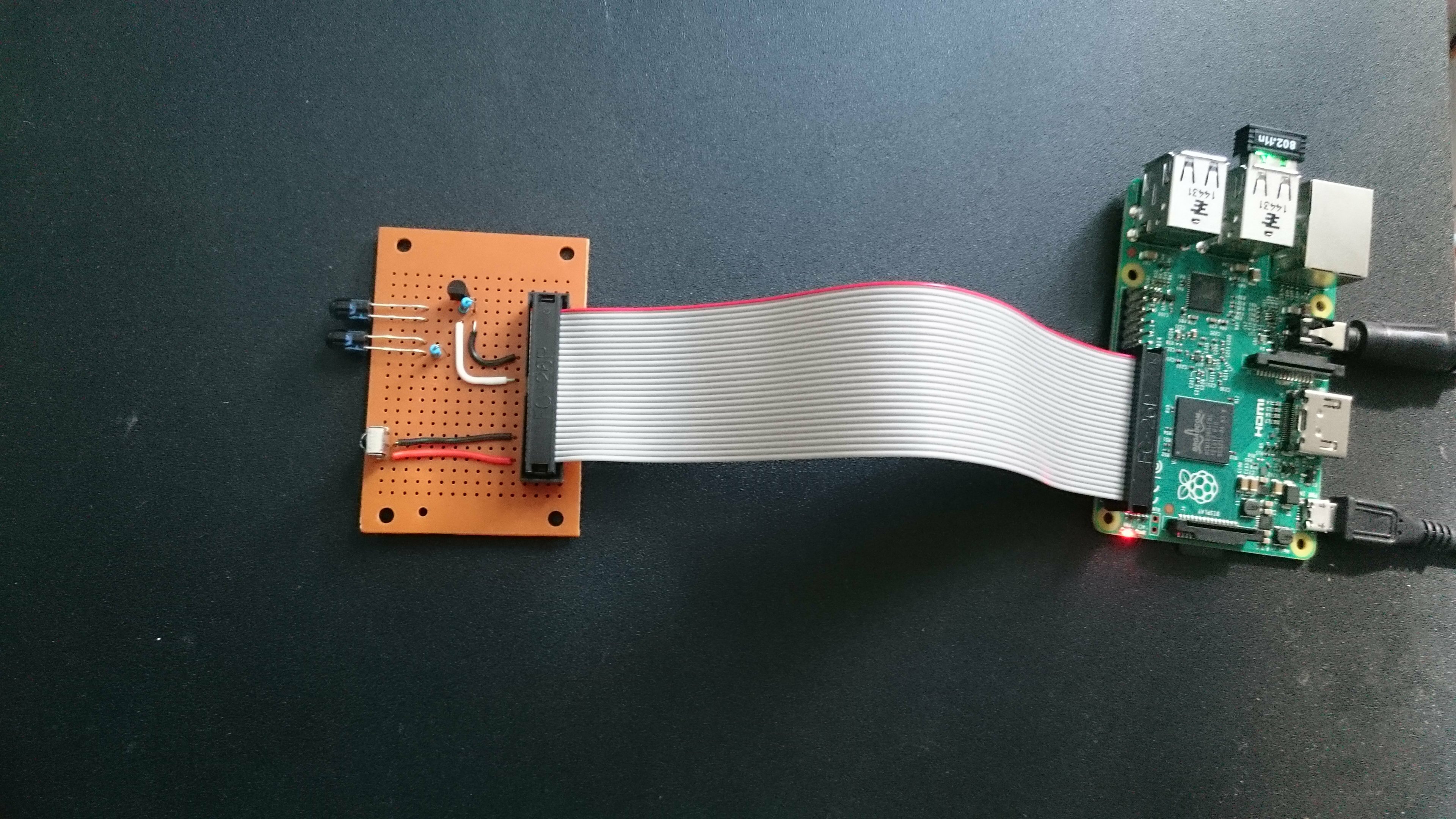
I chose to use a GPIO ribbon cable instead of making a stackable version so that the PI and the remote module could be in a somehow different location and orientated appropriately.
If you are looking for a more “professional” finish, I designed two PCBs using Eagle. One is for the 2×20 gpio version, the other for the 2×13. They can work stacked on the pi or connected via a ribbon cable. Feel free to use them but you should take some time to review them before generating your gerbers and sending them in to production. If you’re wondering about how to do that, I encourage you to check the last tutorial I wrote.
The files for the two versions can be found here.
Handling the IR signals : Software
Preparing the Raspberry Pi
Let’s assume that your Pi was correctly set up and connected to your network, either via ethernet or wifi.
For the package in charge of taking care of our IR needs to work properly, we need to update Raspian OS :
sudo apt-get update
sudo apt-get upgrade
Setting up Lirc
Lirc stands for “Linux Infrared Remote Control”. It is a package that will allow us to decode and to save IR signals for later use. Three of the tools it contains will be most useful to us :
- mode2 : ouputs the pulse/space length of infrared signals to the console
- irrecord : used in order to record IR signals for later usage with lirc.
- irsend : send IR signals from the command line. Signals can be sent once or repeatedly during two calls.
Let’s install it:
sudo apt-get install lirc
We now have to manually configure the driver, setting the gpio pins we will use to receive and transmit the signals.
Edit /etc/modules and add at the end of the file:
lirc_dev
lirc_rpi gpio_in_pin=23 gpio_out_pin=22
The file /etc/modules configures which loadable modules are automatically loaded when the pi starts. More info here.
Add this at the end of the file holding your system configuration parameters /boot/config.txt:
dtoverlay=lirc-rpi,gpio_in_pin=23,gpio_out_pin=22
Next edit lirc hardware’s configuration file /etc/lirc/hardware.conf with the following details:
########################################################
# /etc/lirc/hardware.conf
#
# Arguments which will be used when launching lircd
LIRCD_ARGS="--uinput"

# Don't start lircmd even if there seems to be a good config file
# START_LIRCMD=false

# Don't start irexec, even if a good config file seems to exist.
# START_IREXEC=false

# Try to load appropriate kernel modules
LOAD_MODULES=true

# Run "lircd --driver=help" for a list of supported drivers.
DRIVER="default"
# usually /dev/lirc0 is the correct setting for systems using udev
DEVICE="/dev/lirc0"
MODULES="lirc_rpi"

# Default configuration files for your hardware if any
LIRCD_CONF=""
LIRCMD_CONF=""
########################################################
Reboot your Rasbperry Pi. You should be all set. We are ready to try out our system.
Registering new IR signals
We are going to make sure that our circuit and lirc are working properly by using mode2 to output the characteristics of an IR signal. Start by stopping lirc and launching mode2.
sudo /etc/init.d/lirc stop
mode2 -d /dev/lirc0
Your pi is now listening to IR inputs. Point a remote to the receiver and press any button. The program should output something similar to this, indicating that the reception side of things is all set.
space 14529891
pulse 8451
space 4734
pulse 274
space 884
pulse 403
space 532
pulse 635
space 649
pulse 440
space 680
pulse 462
The first space is the time elapsed until your pressed the button. The first pulse (8451) is the start pulse, used to notify the receiving device that information is coming. Here are some additional informations on how IR signals work.
Now to properly record the signals. We will use irrecord in order to do so. It will record the signals from the remote(s) control and create a .conf file for lirc.
Note that a repository exists where .conf files have been made available for the most common remotes.
We will anyhow create our own. To generate a remote configuration file, first stop lirc so that /dev/lirc0 is available for irrecord to use.
sudo /etc/init.d/lirc/stop
To register a new remote control, you’ll need to press each button of the remote several times (it should be less than 10) until two rows of spots have been filled. You’ll be asked to enter a name for each signal, which will be stored as an hexadecimal code. The output is saved in ~/lircd.conf.
irrecord -d /dev/lirc0 ~/lircd.conf
Sometimes irrecord doesn’t quite get the signal and prints the dreaded message : “Can’t find gap”. Hopefully we can circumvent this problem.
Using the -f option on irrecord will force the raw mode which will create a raw (read plain non-hexadecimal) codes configuration file. You can then try your luck with -a which will analyze the file just created in order to get clean hex codes from it.
irrecord -f -d /dev/lirc0 ~/lirc.conf
irrecord -a ~/lirc.conf
If everything else fails, you can still output mode2’s code in a .conf file.
mode2 -m -d /dev/lirc0 > ~/lirc.conf
Next edit ~/lirc.conf, delete the first value so that the first is the start value we discussed earlier. Complete the file with the following lines:
begin remote

   name  REMOTE_NAME
   flags RAW_CODES
   eps            30
   aeps          100
   frequency    38000

       begin raw_codes

           name COMMAND_1
--- RAW CODE FOR COMMAND_1 ---
           name COMMAND_2
--- RAW CODE FOR COMMAND_1 ---

    end raw_codes
end remote
You can try other frequencies depending on your remote. Note that the indent should be made of spaces not tabs.
When you’re done with that part, make a backup of the original lircd.conf file, copy the new configuration file and restart lirc so that we can send a signal back.
sudo mv /etc/lirc/lircd.conf /etc/lirc/lircd_original.conf
sudo cp ~/lircd.conf /etc/lircd.conf

sudo /etc/init.d/lirc start
Playing it back
Using irsend is pretty straightforward. It can send a signal once by using irsend SEND_ONCE REMOTE_NAME CONTROL_CODE or repeatedly between two SEND_START and SEND_STOP calls. LIST can help by giving you a reminder about the codes available on a remote.
irsend LIST REMOTE_NAME ""
irsend SEND_ONCE REMOTE_NAME CONTROL_1
Is it that simple ? Yes it is. But we don’t want to be restricted to the shell to control our hub, do we ? So let’s continue to the next part.
Setting up a web-application
Remember Alex from earlier ? Well he gave us an open source NodeJs client called lirc_node to interface with lirc. Not happy yet ? Have I mentioned that he also wrote lirc_web, a sample application for lirc_node which I forked in order to adapt it to my specific needs.
Setting up NodeJs
This is going to be quick. Simply download the latest package optimized for ARM (the kind of chip that runs on your pi) and install it!
wget http://node-arm.herokuapp.com/node_latest_armhf.deb
sudo dpkg -i node_latest_armhf.deb
To test your installation type node -v which should output v0.12.7.
Setting up lirc_web
To state the readme :
lirc_web is a nodejs app that creates a web interface & JSON API for the LIRC project. It uses lirc_node to handle communication between LIRC and nodejs.
This project allows you to control LIRC from any web browser – phone, tablet, or desktop. The mobile web interface is responsive and optimized for all sized displays. In addition, with the JSON API, you can control LIRC from any web connected device – pebble watch, myo armband, emotiv EEG headset, or beyond.
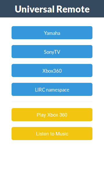
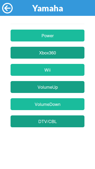
It’s really some great work from Alex. The basic interface uses lirc’s configuration file to list all the remotes and provide a simple but neat interface in order to use the commands registered from the web.
Installing it is as easy as 1 2 3. Navigate to the folder containing your node web apps :
sudo git clone https://github.com/alexbain/lirc_web.git
sudo npm install
node app.js
Et voilà ! The website is now online. To access it, find your local ip with the ifconfig command in the “inet addr” field. The address will be something like http://192.168.2.xx:3000.
If you want the server to get online automatically when the pi boots up, I encourage you to read a great tutorial by -yet again- Alex since I would only be paraphrasing him otherwise : running lirc_web with Nginx and Upstart.
Accessing the App from outside the network : port forwarding
At that point you may have tried to access the website using your cellular-network-connected smartphone and noticed that, damn, it doesn’t work! (I know I did and it took me a minute or two to realize why). So why is that ? Well the ip you got earlier is only worth something inside your network. Between that and the outside world stands your router. If you want an external request to reach your pi you have to set up what is called port forwarding. It means that when your router receives a request on a pre-defined port (a request made on the your public ip visible to the outside world, contrary to the local ip), we want it to redirect (forward) the request inside the network to our pi.
Usually the control interface of routers is accessible at this address : http://192.168.2.1/. Check your manufacturer’s documentation if not. In my case things look like that :
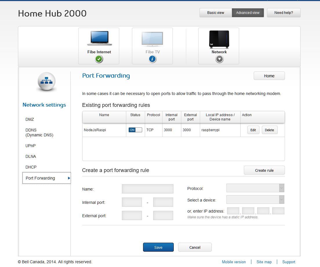
To set it up, create a new rule where the external port is the port from which the request is coming, the internal port is the one inside your network where the request should be redirected to and the local device is, you guessed it, your raspberry pi. If your router doesn’t offer the option to target the device by name you might want to think about setting up a static ip on your pi otherwise the rule will be broken if the pi gets assigned a different address by the router.
You can now access your website from the outside world, yay ! To find your public ip, just google public ip 😉
Additional functionalities
Now that you have the foundation of the system up and running, it’s time to open your favorite text editor and start tweaking things up ! lirc_web provides an awesome starting point for that since it creates an api that makes it very easy to interface with lirc from a web app.
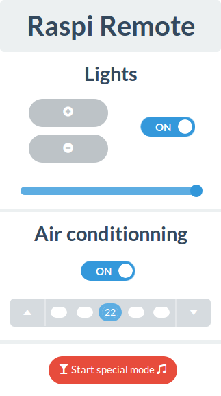
I made my own version of the interface in order to match my needs. It includes control for the AC and the lights, and I added a little button just for fun. You see I’m a big fan of Glenn Quagmire from Family Guy (giggity) and I always envied his ability to turn his house to a love nest at the press of a button. So I made a “special button” that, when pressed, turns on the lights and lowers them to a “comfortable” level, turns on the AC to an “appropriate” temperature and plays this very cheesy music. I used mpg123 in order to be able to start a music player from the command line and subprocess in order to send a command to the bash from the node application.
The forked repository is here if you want to have a look.
Thanks a lot for taking the time to read me. I hope that this guide will be as useful as can be. Don’t hesitate to drop a comment if you spot a mistake or if you have any question!
Great blog entry. Will be studying this in detail
Thank you! If you do, please don’t tell anyone that my front-end is not responsive on desktop. Damn, did I betray myself?! 😉
Hi, Im running raspbian, and Im getting errors trying to load node app.js:
pi@raspberrypi ~/lirc_web $ sudo node app.js
module.js:338
throw err;
^
Error: Cannot find module ‘./router’
at Function.Module._resolveFilename (module.js:336:15)
at Function.Module._load (module.js:278:25)
at Module.require (module.js:365:17)
at require (module.js:384:17)
at Object. (/home/pi/lirc_web/node_modules/express/lib/application.js:6:14)
at Module._compile (module.js:460:26)
at Object.Module._extensions..js (module.js:478:10)
at Module.load (module.js:355:32)
at Function.Module._load (module.js:310:12)
at Module.require (module.js:365:17)
I can’t reproduce the error on my side. Do you have the same error with the original lirc_web app ?
Hello alexis.matelin! Interesting tutorial! I’ve been making a project which sends IR commands to the air conditioner as soon as temperature increases. We’ve got everything working (thanks to alex bain’s wonderful tutorial!), but are now stuck at the last stage, which is getting lirc and node js to talk. We followed all the steps given on http://alexba.in/blog/2013/02/23/controlling-lirc-from-the-web/ and also added .lirc_web_config.json in /home/pi as well as config.json in lirc_web folder as mentioned on https://github.com/alexbain/lirc_web. In this site, under the heading ‘Configuration’, it is mentioned that:
“You may place this configuration file in one of two locations and lirc_web will detect it:
1. Place a file named .lirc_web_config.json in the home directory of the user running lirc_web (global installation)
2. Place a file named config.json in the root of the lirc_web project directory (local / development installation)”
So do we need to do only either of 1 or 2 or both 1 & 2?
And by the way, what is exactly the meaning of ‘root of the lirc_web project directory’? In which folder do we exactly need to place it?
If you think what we have done is correct, then it seems our config.json file is not properly configured! Could you please provide your file so that we can compare your file and alex’s example config.json file to understand how exactly we need to do the configuration? Is there any other file we need to modify and add manually to get a basic webpage? Please help! It gives the following error when we run node app.js:
DEBUG: [SyntaxError: /home/pi/.lirc_web_config.json: Unexpected token]]
Warning: Cannot find config.json
Open Source Universal Remote UI +API has started on port 3000 (http).
His series of tutorials is indeed really great!
As for your first question about the directory in which to place the config file, you need to do either one or the other but not both (only one file would end up being recognized anyway but I’m not sure which one so let’s not complicate things for no reason). The root of the lirc_web directory refers to the top folder of the repository you cloned (so the one that contains package.json, app.js the README the Makefile etc.). But my guess is that you installed lirc_web globally by doing “npm install -g lirc_web” thus you didn’t clone the repo directly. In that case you can run “npm list -g” which will give you a list of the applications installed globally with their location path.
I see that you chose to put the config file in your home directory (/home/pi). That’s quite alright and don’t be fooled by the error message, it is indeed being found but you have an error on your syntax, check your macros as it’s the only part of the file that contains arrays (precisely I think that you closed an array twice since the unexpected token is “[“).
Let me know how it turns out and if you need any additional information.
Thanks ever so much for your prompt and clear reply! Things have worked out now… there were a few things i was doing wrong…
1. First of all, i hadn’t changed the name of my remote from its default name ‘/home/pi/lircd.conf’ simply because i didn’t know how to do it! Then i found this post on https://forum.pimatic.org/topic/235/howto-receive-transmit-infrared:
“After you successfully recorded your own remote and copied it in /etc/lirc/ you may want to give it a name in the config file so you can later send commands like irsend SEND_ONCE KEY_MUTE.
1. Stop lirc if running: sudo /etc/init.d/lirc stop
2. Open config file sudo nano /etc/lirc/lircd.conf You can change the name of your remote by changing (guess what:) the line ‘name’.
3. Close and save config file and start lirc again: sudo /etc/init.d/lirc start”
which helped me change my remote name. This was helpful because i think the backslashes in the original name were somehow not letting it work properly.
2. The second thing i did was to remove the ‘socket’ line from config.json file. I read in alex bain’s comments that this functionality was added for OSMC and since i’m not using any such thing, i just thought about trying removing it and it worked! Though i would love to know more about what exactly that line does if you would like to share…
3. I also removed the multiple copies of the config.json file that i had made in different directories and just kept the one named .lirc_web_config.json in the /home/pi directory as you said only one is needed.
These 3 things seemed to work and now i can send commands to my aircon from a browser inside the network. The next step is to make it accessible from outside the network… I see that you have used port forwarding for that purpose… But as i am making this project as part of a college project, it won’t be particularly good for me to tweak the routers in college… Hence i’m looking for a safer alternative and i found this post: https://www.raspberrypi.org/documentation/remote-access/access-over-Internet/internetaccess.md and hence now studying about ‘Weaved’…
Thank you once again for taking the time to help me out and let me also mention that though alex’s tutorial is gr8, there are many things in your post which have helped make alex’s tutorial clearer, for eg., the way you explained the meaning of mode2, irrecord or irsend and what info the files we are tweaking actually store and how ir signals work. So keep up the good work!
Hey I’m glad that I turned out for the best. As for the port forwarding problem, check out Ngrok it’s a great tunneling service (meaning that it will create a tunnel of sort that will allow you to access your server from outside the network). That’s what I use when I need to do some testing and I’m not on a network that I can control. One command and bam you get an address accessible from anywhere it doesn’t get any easier.
Link here (funny thing: I just spent half an hour looking for it because I was thinking of Nginx for some reason –): https://ngrok.com/docs#expose
About the socket thing, from what I understand from the doc (http://linux.die.net/man/8/lircd): lircd’s job is to decode the ir signals and to then make the result available to other services on the OS. It does so by streaming the result to a socket (not a web socket like the one used to access websites or whatnot but a domain socket, basically a hose of streaming information accessible to services on the OS). Since in unix systems everything is represented as a file, this socket is embodied in the file “/run/lirc/lircd1” whose address you provide to lirc_web so that it can plug in and listen on the decoded ir signals and act accordingly. I guess that by removing the line you fell back on some default parameter that worked better in your case. But I might be mistaken.
Anyway good luck if it’s a project for college. I’ll still be available if you have any more inquiries along the way. Are you studying computer sciences?
Nope, Electronics… but just the IoT boom being the buzzword nowadays pulled my team and me towards an RPi based project…
& thnx once again! Will read more about Ngrok… and find out which out of Weaved and Ngrok suits us better…
Indeed the big hype seems to be take x, add some sensors and electronic control, pump the data to some amazon decentralized service, feed it to some fancy machine learning model, …, profit.
You might have heard of it but the Photon is pretty great to prototype IoT projects when you don’t need all the power of a pi. The ESP8266 provides a very good low cost alternative too.
can i replace P2N2222 transistor with other?? if yes, thn please give me the name of transistor by which i can complete this project…
You can replace the transistor by any general purpose NPN transistor (a mosfet would do the trick too). You could even use a PNP transistor but in that case it would be placed before the LEDs (an NPN is usually used to connect/disconnect the ground – sink the current when a PNP can handle higher currents and thus switch the incoming current). As for the values, there are a lot of components that will fit that description so I can’t give you one specifically. You need to read the datasheet of the 2N2222 and compare its parameters with the components you have access to.
We used a simple BC547 & it worked as well!
Some more info on how to look for the right transistor.
The values of interest here are:
– the collector-emitter breakdown voltage (the maximum voltage that can be applied between the collector and the emitter of the transistor). General purpose transistors are usually rated around 40/60V so that’s plenty enough since we’ll be feeding 5V.
– the base-emitter saturation voltage: this is the voltage that needs to be applied to the base so that the transistor “switches on” and lets the currents flow from collector to emitter. Anything < 5V works. With the P2N2222 the value is 2V which is why we use a resistor between the base and the pin.
http://www.digikey.com/product-search/en/discrete-semiconductor-products/transistors-bjt-single/1376376
http://media.digikey.com/pdf/Data%20Sheets/ON%20Semiconductor%20PDFs/P2N2222A%20Rev3.pdf
my IR Receiver is not generating any value. what should be the problem?
And I know only Python so Anybody having python coding for this same task??
“irrecord -d /dev/lirc0 ~/lircd.conf” command is not working for my daikin AC remote.. it is showing ” irrecord: could not find gap , irrecord: gap not found, can’t continue “.
This command is working fine with my TV remote and generate lircd.conf file.
What should i do for my AC remote . How can i generate lircd.conf file for my Daikin AC.
# Please make this file available to others
# by sending it to
#
# this config file was automatically generated
# using lirc-0.9.0-pre1(default) on Wed Dec 14 09:35:06 2016
#
# contributed by
#
# brand: /home/pi/lirc2.conf
# model no. of remote control:
# devices being controlled by this remote:
#
begin remote
name /home/pi/lirc2.conf
flags RAW_CODES
eps 30
aeps 100
gap 4430
begin raw_codes
name KEY_PLAY
4386 582 1594 579 1596 578
1595 583 1593 575 513 574
509 580 1592 578 511 577
510 576 511 576 511 576
511 576 1604 565 1608 574
506 554 1627 543 546 566
512 576 512 574 511 575
514 549 536 574 1598 552
1622 551 1622 552 1622 552
1621 552 1622 551 1623 550
1623 551 540 548 537 550
537 550 538 548 538 549
538 549 538 549 538 548
539 548 1624 550 539 549
1623 550 539 549 538 549
538 549 538 549 544 545
536 520 567 550 1622 551
538 549 538 550 537 578
509 549 1623 551 538 550
537 550 537 550 538 554
533 549 538 549 538 573
514 550 537 550 537 574
513 575 512 576 511 549
538 573 515 574 1597 577
1598 571 7958
name KEY_VOLUMEUP
4418 575 1606 569 1602 568
1605 567 1600 572 518 569
517 569 1607 565 524 536
547 567 517 568 526 564
519 568 1601 573 1598 581
507 569 1601 571 518 546
541 568 519 568 518 569
518 566 520 545 1626 571
1602 571 1602 571 1602 571
1601 572 1601 572 1601 572
1603 571 515 570 519 568
518 584 503 568 518 568
519 568 520 567 518 568
519 568 1601 575 1598 572
519 568 1601 573 518 542
546 568 517 569 518 569
520 566 519 568 1601 574
516 569 518 568 519 568
519 568 1601 588 502 569
518 568 521 541 549 564
517 569 518 569 518 581
506 568 518 569 1601 588
1586 572 1602 572 518 568
519 568 519 568 1602 571
1602 572 7955
name KEY_VOLUMEDOWN
4422 581 1601 577 1596 580
1597 579 1602 574 512 577
511 578 1596 580 512 576
512 577 512 576 512 577
513 576 1601 579 1597 579
509 579 1598 578 511 578
510 592 496 577 512 578
510 582 507 576 1598 580
1599 578 1602 574 1598 579
1598 579 1598 579 1598 583
1594 579 512 576 512 578
511 577 512 576 509 578
514 577 512 577 512 576
512 577 1598 579 512 577
512 576 512 577 512 577
512 576 512 577 512 577
512 577 512 576 1595 608
487 577 511 577 512 577
512 577 512 576 1599 578
513 576 512 578 512 576
512 576 513 576 513 576
513 576 512 579 508 578
1599 579 513 577 511 577
512 577 512 577 512 576
513 576 7965
name BTN_MODE
4428 578 1601 575 1601 575
1602 574 1602 576 514 573
516 571 1602 575 515 582
507 572 516 573 515 573
516 572 1601 576 1605 576
512 576 1603 573 515 570
517 573 514 572 516 576
518 567 520 569 1601 575
1602 575 1601 587 1589 576
1602 574 1602 575 1601 576
1601 575 515 574 515 573
515 573 515 574 515 573
515 574 515 574 514 574
519 570 1600 577 515 600
489 573 514 574 515 574
514 575 514 574 514 575
513 575 514 575 1600 577
514 575 513 575 514 574
514 575 514 574 1602 575
514 575 514 574 514 575
514 575 513 574 515 574
515 573 515 574 515 573
1607 570 515 573 516 572
517 572 516 572 517 560
527 575 7965
name KEY_0
4424 583 945 1226 387 684
532 580 1601 576 1599 579
513 576 511 577 1597 581
511 554 534 578 511 578
511 578 513 575 671 1547
1567 578 505 577 1598 580
517 577 506 576 512 578
511 577 512 577 512 577
1598 580 1598 554 366 311
229 1298 1597 580 1598 579
1598 580 1598 580 1598 580
511 577 512 577 512 577
512 577 512 548 542 575
302 787 513 577 512 577
1598 579 513 576 513 576
513 576 513 576 513 577
512 576 513 577 513 576
520 568 1273 959 460 574
515 576 513 575 514 575
1600 578 514 576 513 577
512 576 513 577 513 576
513 575 514 576 513 577
513 576 513 575 1134 1045
512 576 514 577 512 576
514 576 1605 573 1599 579
6346
end raw_codes
end remote
Hi Guys,
Using universal remote to access the Toshiba A.C on that time, I have received above values in config file using that values, I have pass the command to ON and OFF the A.C. But it wont works properly.Could you please guide me what i did wrong.I have using TSOP1738 Receiver. Remaining all whatever u have mentioned in circuit those things only I have used. I have followed same procedure for Panasonic T.V Remote controls it will work fine ,I can able to pass the value via IR to turn ON & OFF the T.V. Please help me out this problem, thanks in advance.
For controlling multiple devices, this setup would require multiple IR receivers, is there any way to program them separately ?
Hello Sumit. I’m not sure what you mean by multiple IR receivers. You can record the signals from different remotes (which themselves control different devices) using only one receiver and register them in the lirc conf file following the procedure described in Registering new IR signals
For anyone having trouble with Lirc_web displaying only macros but no buttons at all take a look at this https://github.com/alexbain/lirc_web/issues/57 this solve the problem for me. I wanted to ask you a question Alexis… great tutorial by the way! I am new into this raspberry business but I managed to set up my a/c to respond to LIRC then I set up LIRC_WEB and was able to use the web interface to turn on or off my devices. My question is, how did you change/tweak the display in LIRC_WEB I try to see your code but I am not sure how can I apply similar stuff to my lirc_web. As I told you I am kind of new to this and any help would be appreciate it. Thanks