This project was born from a very common problem: our office’s floor is equipped with one bathroom that can’t be seen from every desk. Ensues unnecessary back and forth when someone walks to the bathroom only to find it occupied.
The solution ? A simple bathroom monitoring system composed of two devices:
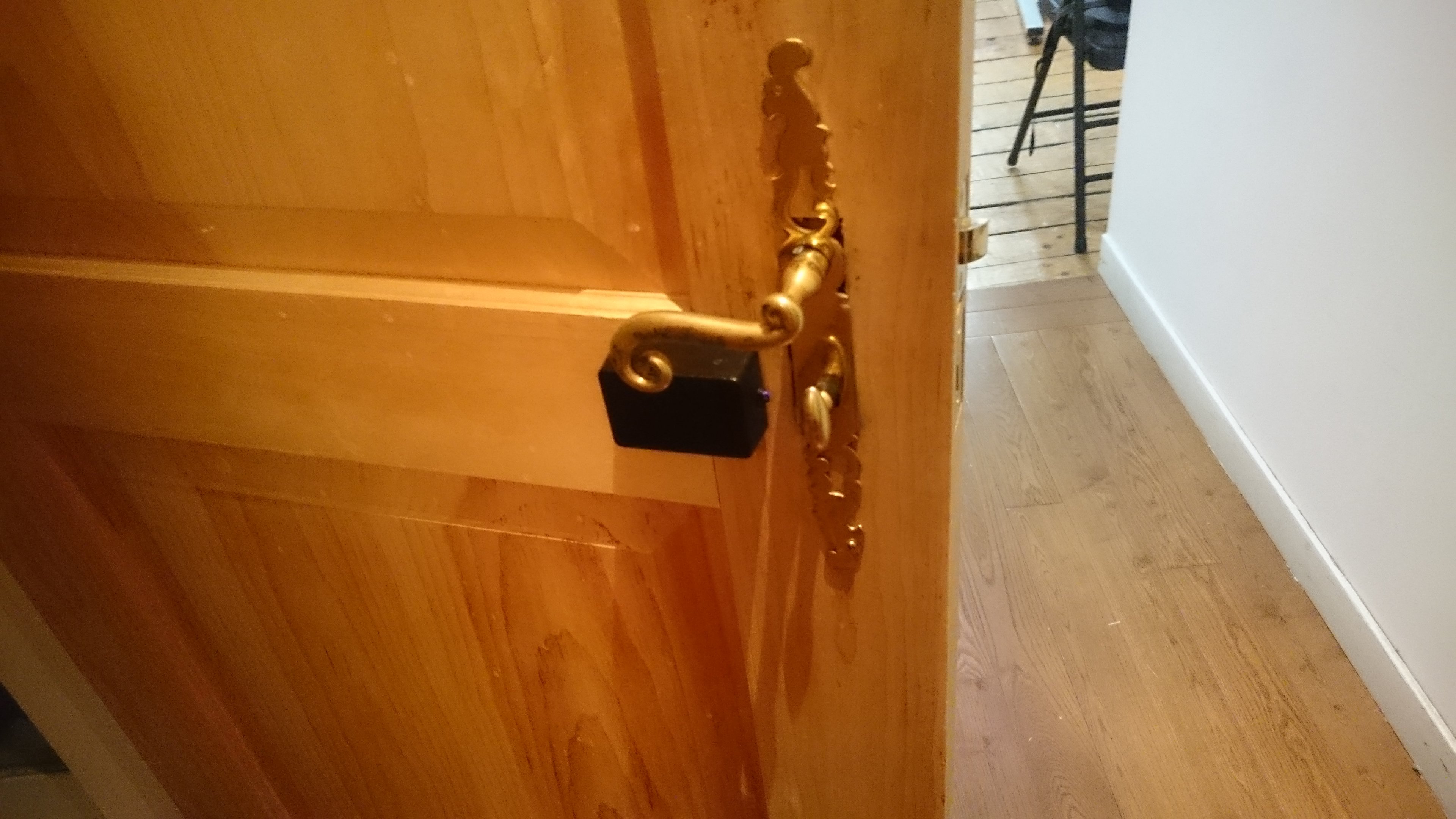
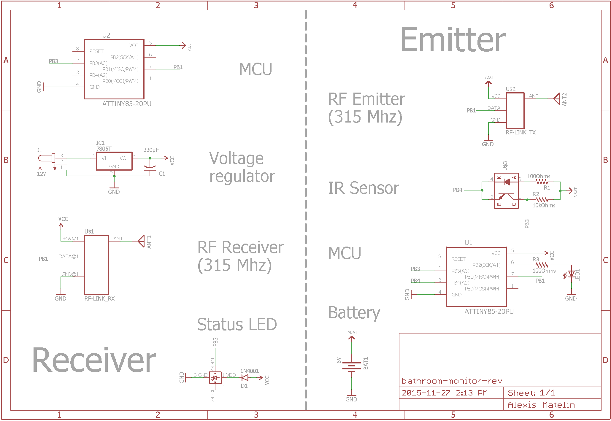
- An emitter placed on the inside of the door of the bathroom to monitor. An infrared sensor is directed toward the lock’s knob. A piece of black tape is applied on the knob. The idea is the following: when the door is unlocked, the knob’s metallic surface is facing the sensor and reflecting a fair amount of IR light. When the door is locked, the taped part of the knob is now facing the sensor. Since the tape is black, the amount of IR light reflected decreases: we know that the door is locked. We use a radio emitter module to send the value read from the sensor to the receiver. A small Atmel microcontroller (the ATtiny85) acts as the brain of the system. The device runs on 4 AAA batteries and is put to sleep 5 seconds every time a reading is sent in order to save power.
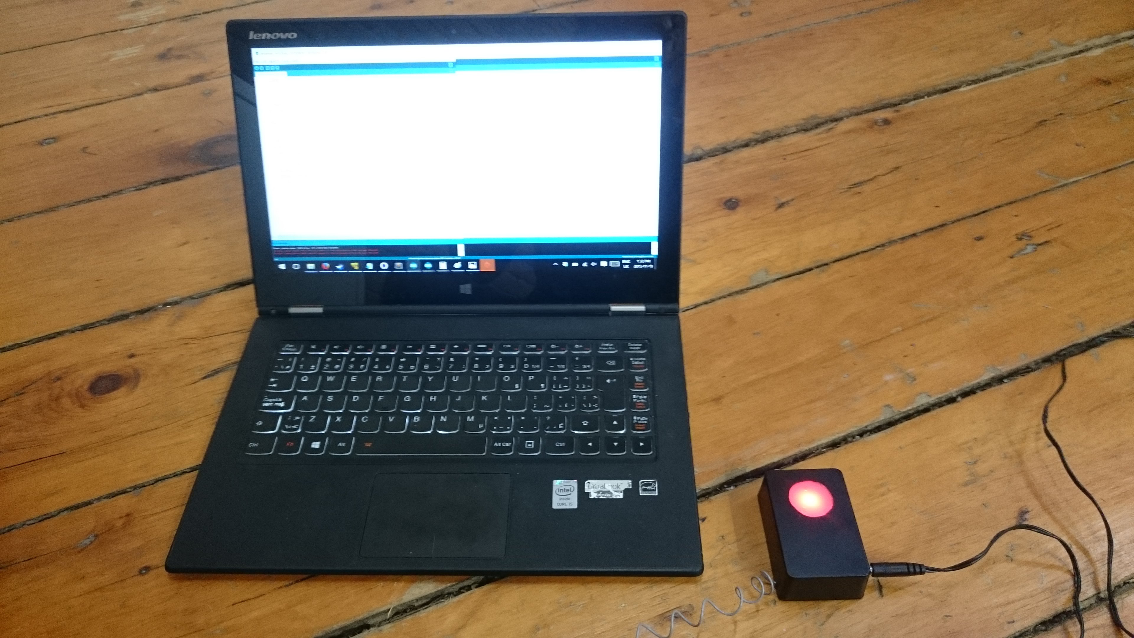
- The receiver is used to display the status of occupancy of the bathroom remotely. It is built around the same microcontroller as the emitter. A RF receiver picks up the readings from the emitter. Depending on the value received, we light up an RGB LED in green or red. This device runs on a wall wart since the LED is constantly turned on.
Both devices are equipped of an ON/OFF switch.
Walkthrough
Components list
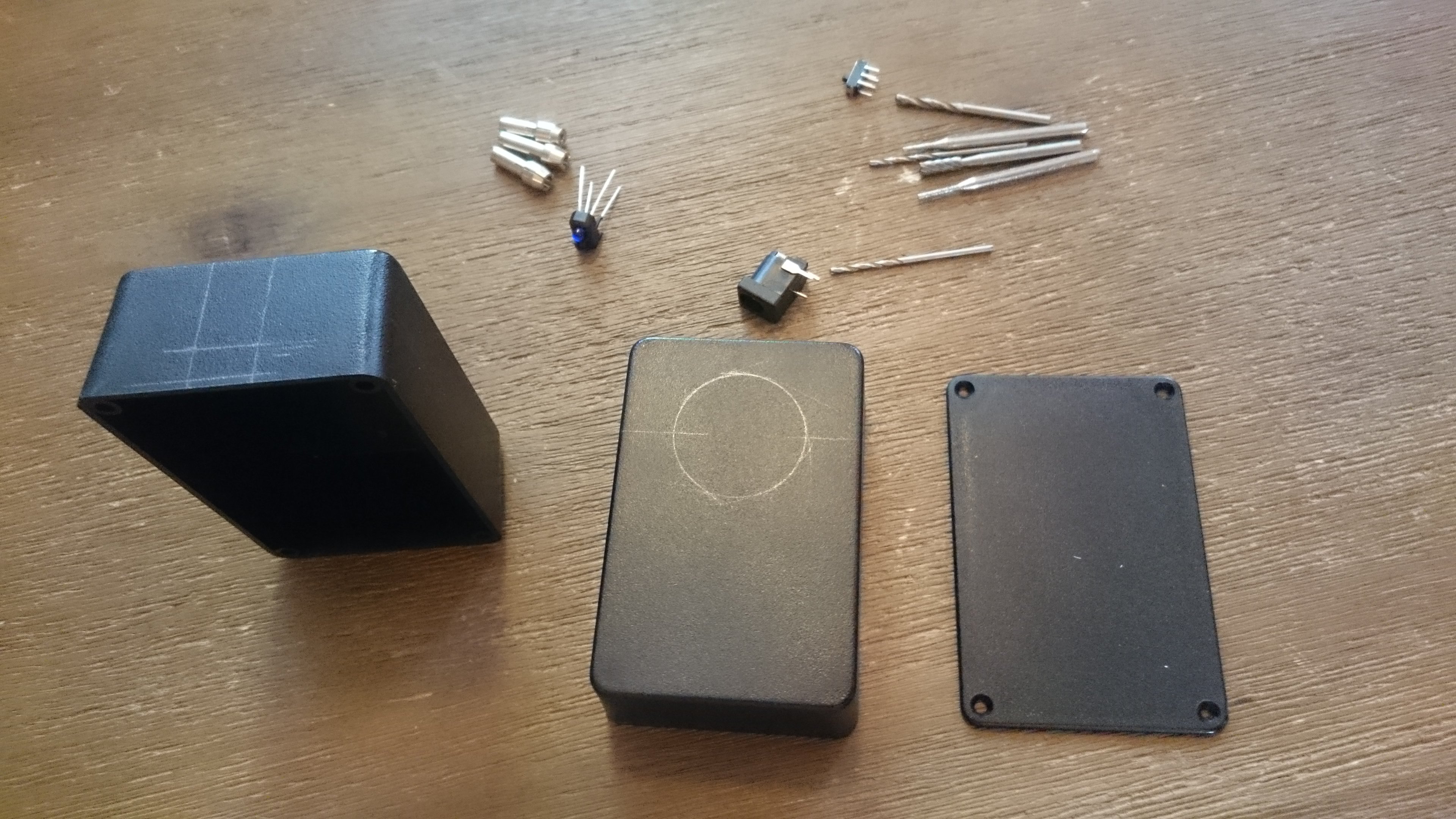
The components were chosen so that the hole project would be as low cost as possible. This is why radio has been retained as a means of communication, and also explains why the ATtiny was so appropriate too. Using standard project enclosures allow to drive the costs down as well.
- 2x Arduino Uno (possible to work with only one, doesn’t need to be a Uno)
- 2x ATtiny85
- 1x RF Link Receiver (4800bps, 315/434Mhz)
- 1x RF Link Emitter (4800bps, same as receiver)
- 1x Reflective IR sensor
- 1x Neopixel mini PCB
- 1x L7805 Voltage regulator
- 2 8 pins DIP sockets
- 1x 5mm LED
- 1x 330μF capacitor
- 1x 1N4001 diode
- 2x 100Ohms resistors
- 1x 10kOhms resistor
- 1x 2.1mm power jack
- 2x ON/OFF switches
- 1x 12v wall adapter power supply
- 1x 4 AAA battery holder
- 4x AAA batteries
- 2x project enclosures
- 2x perfboards
+ breadboard
+ jumper wires
+ soldering equipment
+ hot glue gun
+ cooking oil spray
+ rotary tool

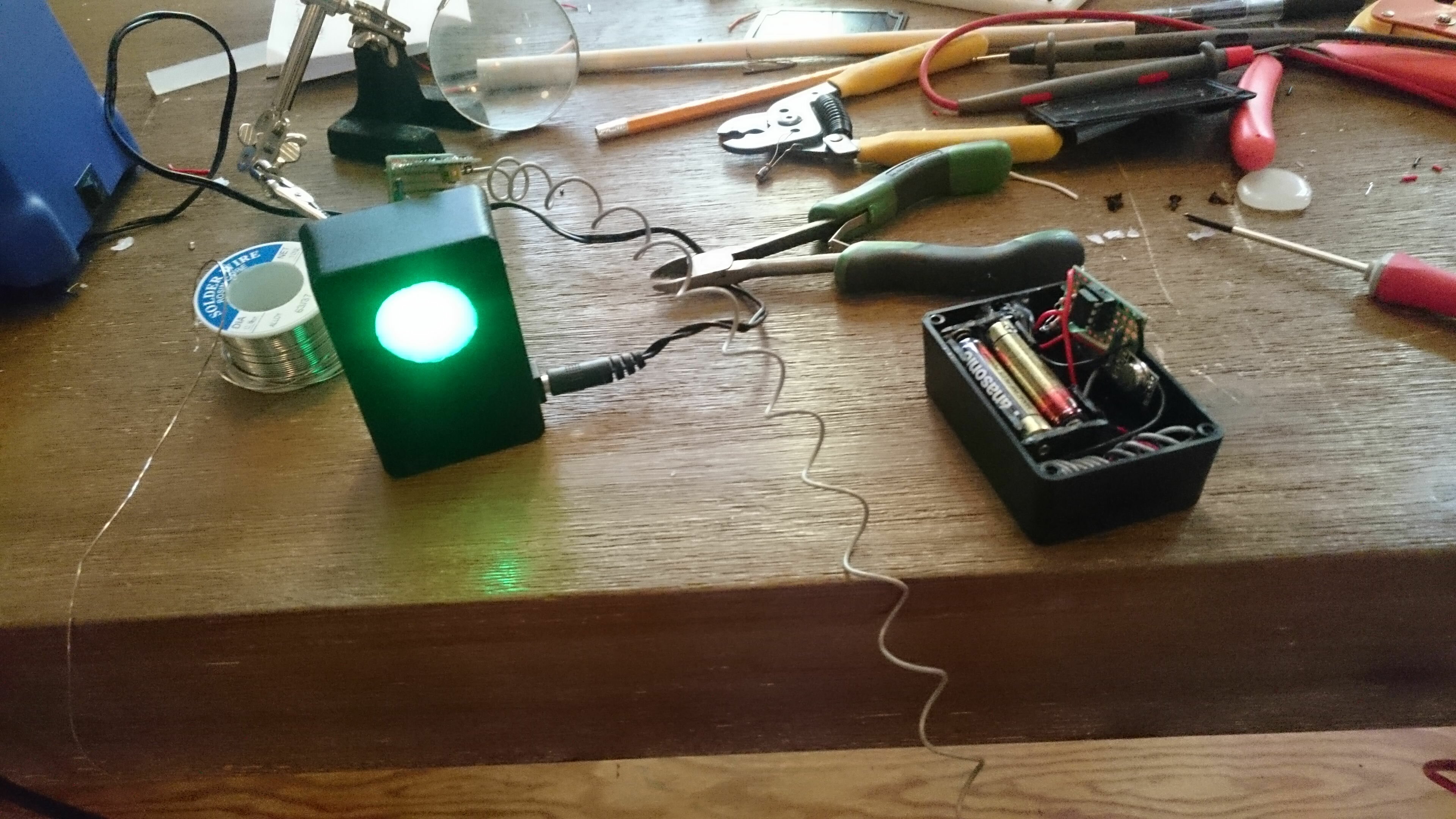
Note: the picture doesn’t show the exact same components as in the list. When in doubt, trust the list not the picture.
Testing the circuit
The first thing we need to do is to test our components individually in order to make sure that everything is working properly.
Initial set-up
Since you are following this tutorial you are probably already used to uploading code to an Arduino. But this time it is a little different since we need to flash the ATtiny chip itself. You obviously can’t use a usb cable directly like we do with the Uno.
Follow this guide in order to flash your device and test it with the famous blink sketch.
Now that you followed the guide, you should know about cores packages. This is where things get messy. In order to use one of the libraries that we require, we need to install a specific core package on a (very) specific version of Arduino. And to add to the complexity, the ISP sketch that we upload to the Arduino the serves as a bridge between the computer and the ATtiny will need to come from yet another version of Arduino.
So let’s get to it. You shouldn’t be lost if you follow the following steps:
- Download the Arduino IDE version 1.0.0 and 1.6.0. Be careful here, not the 1.0.1, and not the 1.6.2. 1.0.0 and 1.6.0. Less hair pulling will ensue if you make no mistake here.
- Download the core package for Arduino 1.0 and set-up following the procedure explained in the guide.
- Download and install the Manchester library for the Arduino IDE 1.0.0. This page from the Arduino website will help you with that if need be.
- Download and install the Neopixel library for the Arduino IDE 1.0.0.
- Upload the ArduinoISP example sketch from the Arduino IDE 1.6.0 to the Arduino used as bridge.
- Connect the Arduino to the ATtiny following the fritzing diagram in the guide. In Tools->Board select ATtiny85 @ 8 MHz (internal oscillator; BOD disabled).
- Upload you sketch to the ATtiny from the Arduino 1.0.0 IDE.
Not lost yet ? Let’s move on.
RF emitter/receiver + Arduino
Using an Arduino will help us debug the circuit more easily if something goes wrong. Only when we made sure that our components are not faulty will we start using the ATtinys.
Basic communication
Sending data over bluetooth is not very different from using a Serial connection. You just send something and in and it comes out on the other side unaltered. With RF, things are quite different. It is very difficult to get unscrambled information on the receiving end, so forget about simply using println().
Hopefully great minds worked at solved this kind of problem before us and came up with very efficient solutions. One of them is the Manchester encoding. The chief advantage of Manchester encoding is the fact that the signal synchronizes itself. This minimizes the error rate and optimizes reliability.
We will test the modules using two Arduinos. You might not have access to two different microcontrollers in which case you can use the ATtiny directly to test your set-up (but don’t forget to use the right pin numbers).
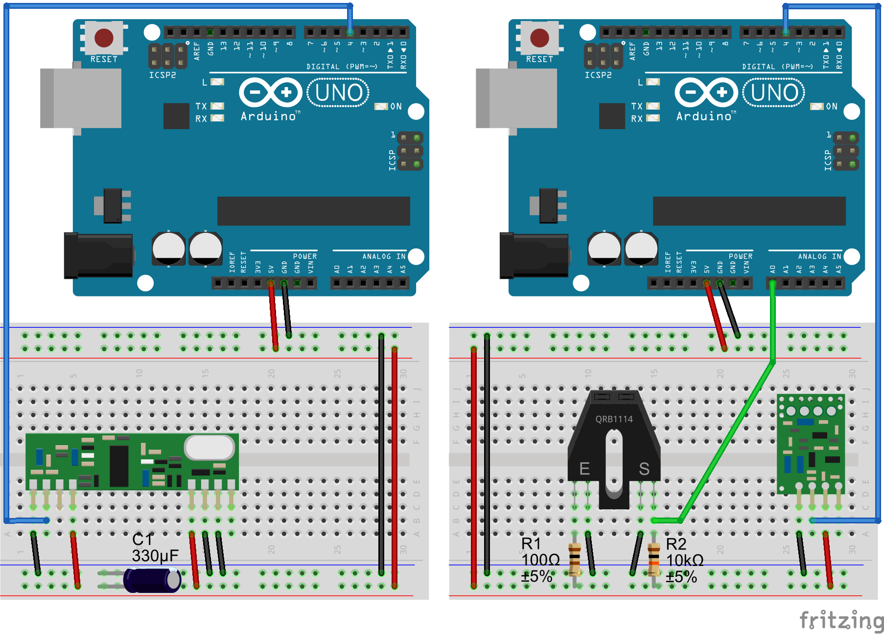
The circuit is simple: we simply provide power to both modules and use a 330μF decoupling capacitor on the receiver side. This capacitor filters parasitic signals on the power line and greatly improves the reception.
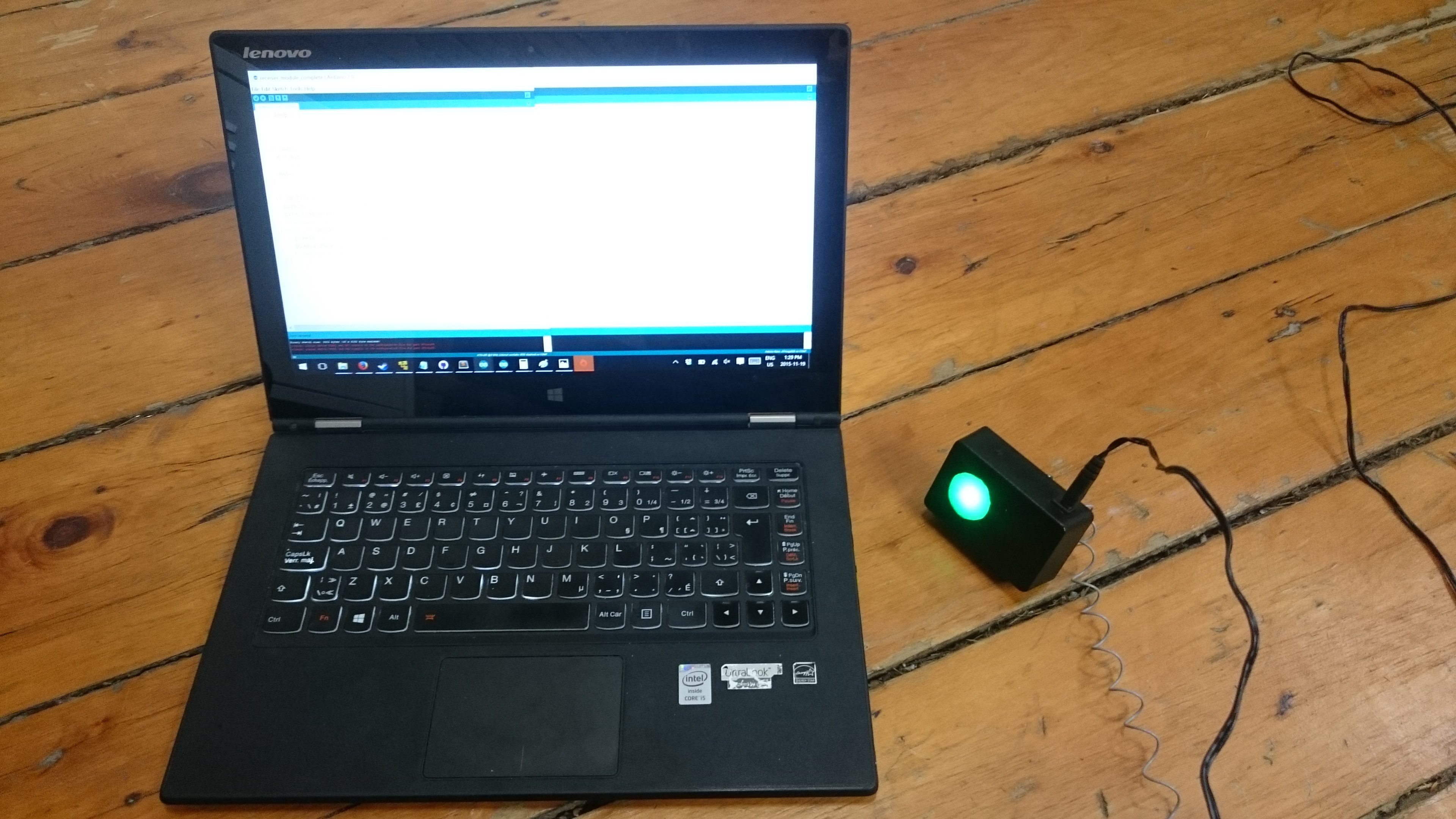
Upload this code to the emitter device and that one to the receiver. The emitter simply increases a counter each time its main loop is executed. The value of the counter is sent using the Manchester library to the receiver which prints it to the Serial console. Both devices use their built-in LED as a communication status light.
Adding the IR sensor
The IR sensor is composed of two parts: an IR LED and a phototransistor reactive to a specific wavelength. The LED is wired as any other: in serie with a current limiting resistor.
We use a pull-up design to connect the sensor. Remember that the sensor is simply a phototransistor: the IR light it is subjected to creates a small current to the gate, provoking a larger current to flow between the collector and the drain. It means that when no light is applied to the sensor, it basically acts as a resistor of near infinite resistance.
Now what happens to the value measured on the analog pin? When no light is applied to the sensor, its resistance is high and the current flows to the analog pin: it reads a high voltage (5v or 1023 in analog terms) – it is pulled up.
When the sensor starts receiving IR light, its resistance decreases and current start flowing through it: less current flows through the analog pin and the value measured decreases.
Upload the following code to the emitter microcontroller. It is a variation of the last one: instead of sending the value of the counter, we send the readings from the analog pin.
Adding an antenna
You might have seen that we left out a pin on each RF module: the Antenna pin. You can increase the range of the system by hooking up a piece of wire to it.
How can we choose the length of the wire ? By following the formula of course!
Let L be the length of the wire, f the frequency of the radio signal we are transmitting and c lightspeed.
λ = c/f
λ = 299’792’458/315’000’000
λ = 0.9516
L = λ/4
L = 0.2378m = 23.78cm
The wire used as antenna should be approximately 24cm long. Make your tests in order to see what works out best for you: type of wire, coiled or not etc.
Switching to the ATtiny85
Now that we have the basics laid-out we can start working with our tiny microcontrollers.
ATtiny + Neopixel
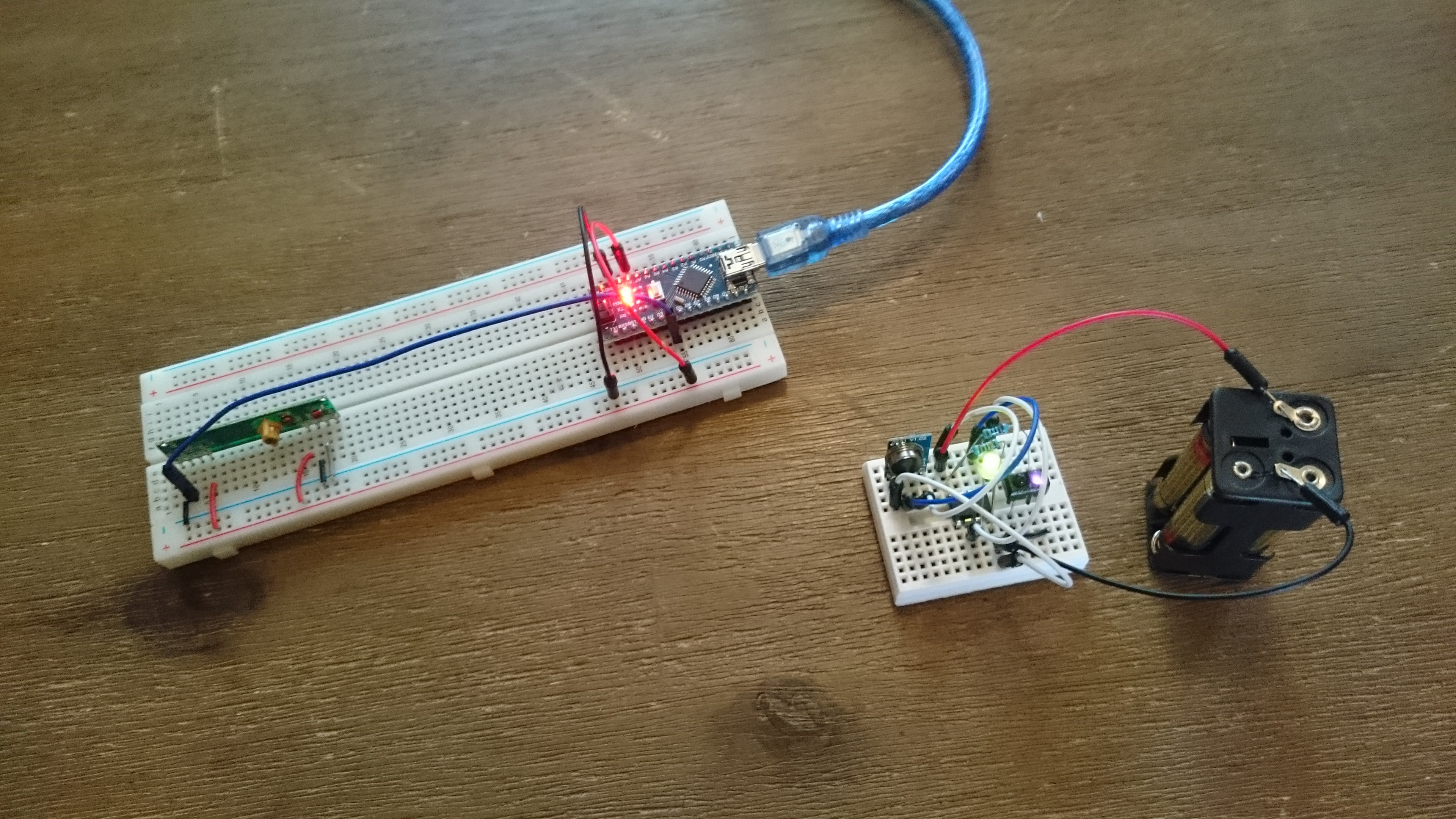
We will begin by ensuring that the Neopixel’s library works well with the ATtiny. It is a good excuse to lay out the external power supply using the power jack, the voltage regulator and the wall wart. We use a voltage regulator because our circuit needs 5v to work, whereas the wall wart provides a 12v output.
Assemble the circuit on a breadboard.
Upload the corresponding code using the method described in the guide. Your Neopixel should start a nice rainbow-like animation.
Emitter circuit
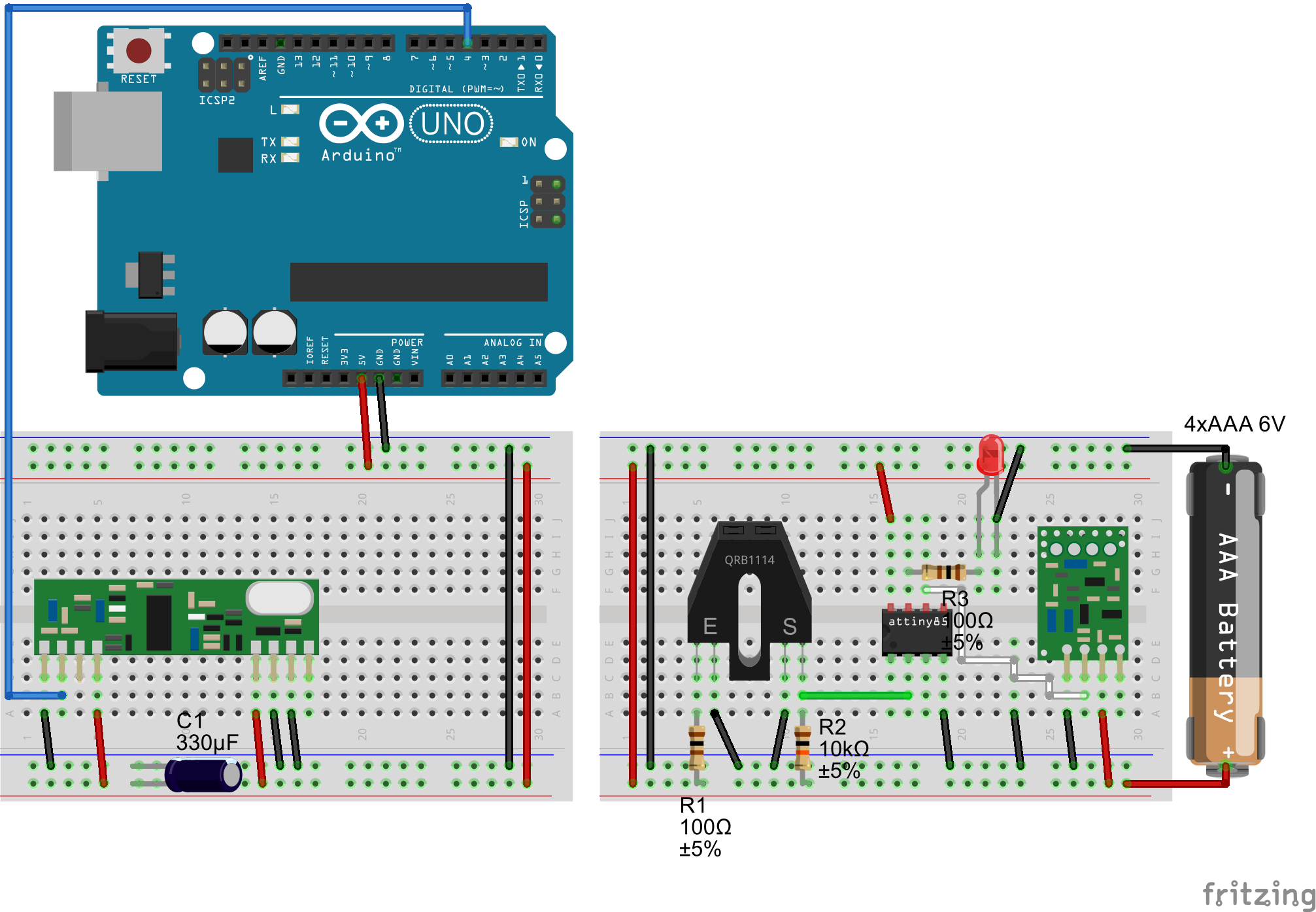

We start by testing the emitter so that we can still use an Arduino on the receiver side and print the incoming messages for debugging purposes. This corresponds to the first Fritzing diagram.
You can use the same code as before as it includes pin numbers for the ATtiny. As before, you should see the value read from the sensor on the Serial console of the receiver.
When you are done with your tests, move on the the final version of the emitter circuit.
The circuit is a little different: instead of connecting the cathodes of the IR Sensor directly to the ground, we connect them to a pin of the ATtiny. This way we can control the power going to the sensor: when the ATtiny pin is set to **HIGH**, no current flows since the sensor is connected to two positive traces. When the pin is set to **LOW**, it acts as a sink and current can flow from the sensor to the ground.
Upload the final version of the code for the emitter.
What it does it implement a **sleeping mechanism** so that we can save as much power as possible on the device since it runs on batteries. After each active cycle, the device is put to sleep for about **10 seconds**. We don’t use the status LED anymore again for energy conservation purposes. When the device wakes up for an active cycle, it **switches on** the power for the IR sensor, takes a **reading** and sends it **25 times**. We do that because depending on the conditions the RF link can be very weak so we want to ensure that the message is received before going back to sleep. The power is then disabled by setting the sensor sink pin to HIGH and the devices goes to sleep for about 10 seconds.
Receiver circuit
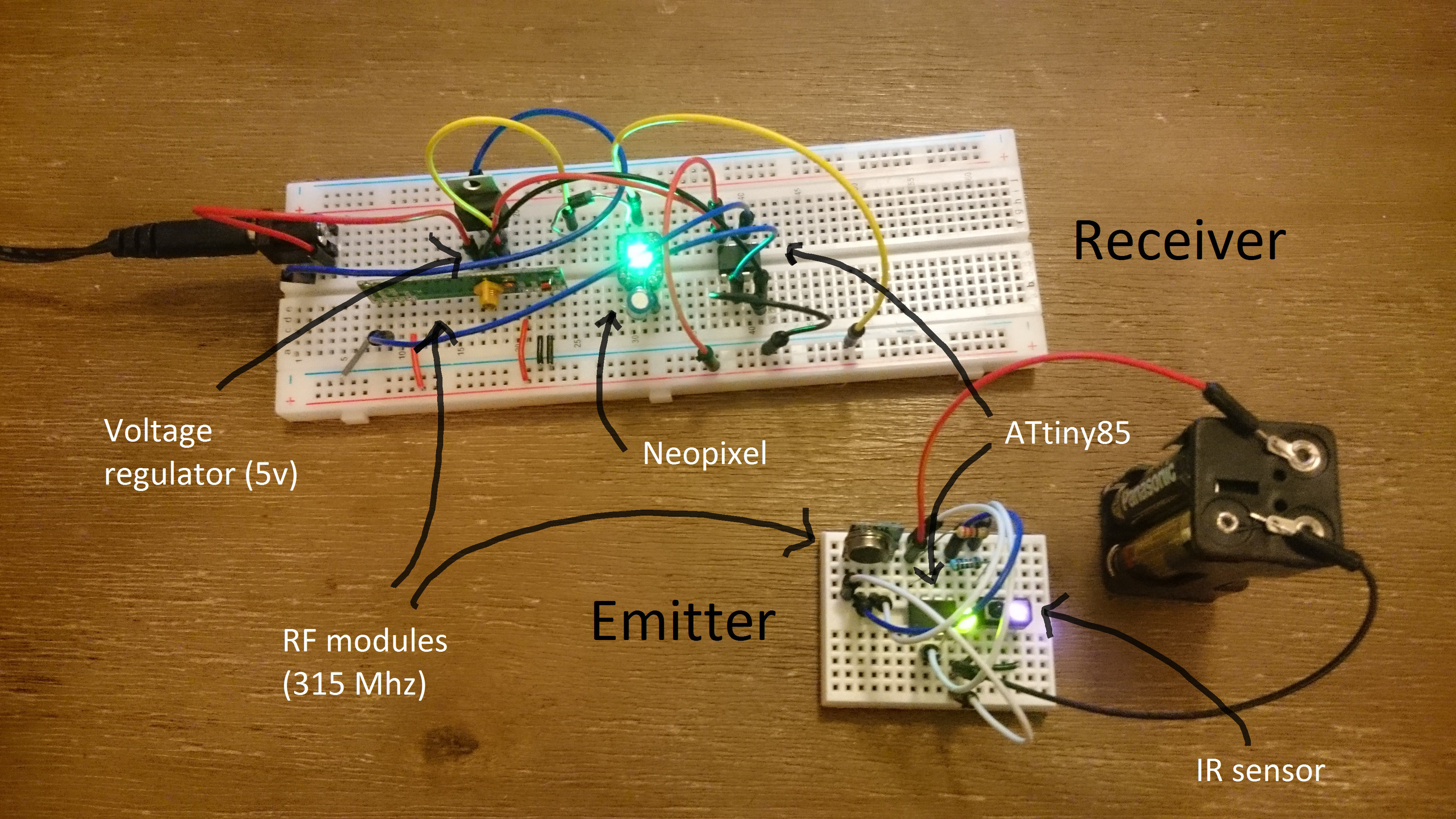
Time to go full ATtiny! Nothing complicated here: the ATtiny is substituted to the Arduino on the receiver side and we add the Neopixel that we tested earlier.
A sign that we’re getting close the end, you can upload the definitive code to the receiver. It uses the IR sensor’s value received to light up the status LED in either green or red.
If it works, congratulations the hardest part is behind you!
Final assembly
Enclosures carving
Let’s prepare our enclosures so that they are ready to receive their respective components.
On the emitter, we only need room for:
- the IR sensor,
- the ON/OFF switch.
And on the receiver we want:
- a circular hole in the front pannel will be used for the light diffuser of the status LED,
- access to the ON/OFF switch,
- room for the power jack to pop out,
- a little incision so that the antenna can be deployed outside.
Make your measurements and use the rotary tool (or any other tool that you have access to and that will do the job) to make the necessary cuts in your enclosures.

Emitter device
Soldering the circuit
We can now make it a bit more permanent. Heat up your soldering iron and gather your components. This circuit schematic will help visualize the circuits you need to make.
We start with the emitter because we’ll have to calibrate some values in the receiver code once the emitter will be placed on the door. For the calibration we will print the values from the receiver which is why it is a good idea to keep this part of the project on a breadboard for now so that you can easily reconnect it to an Arduino.
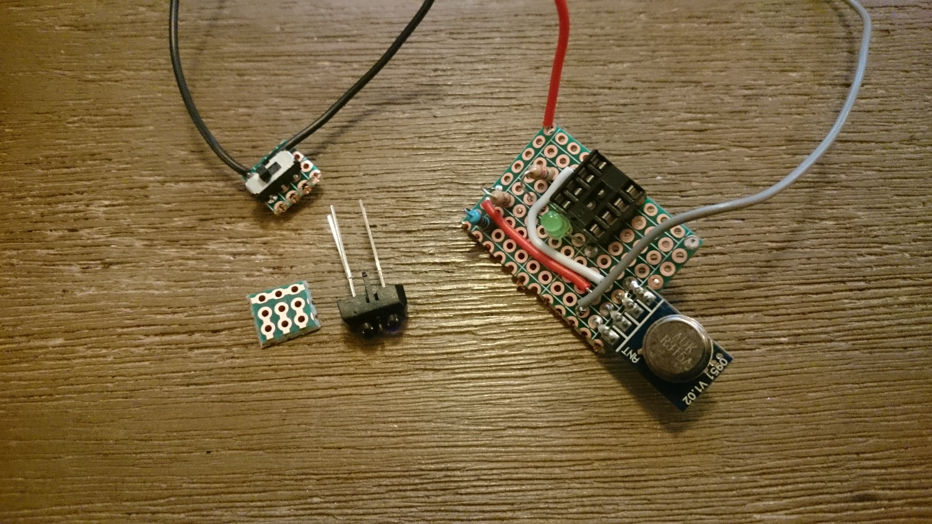
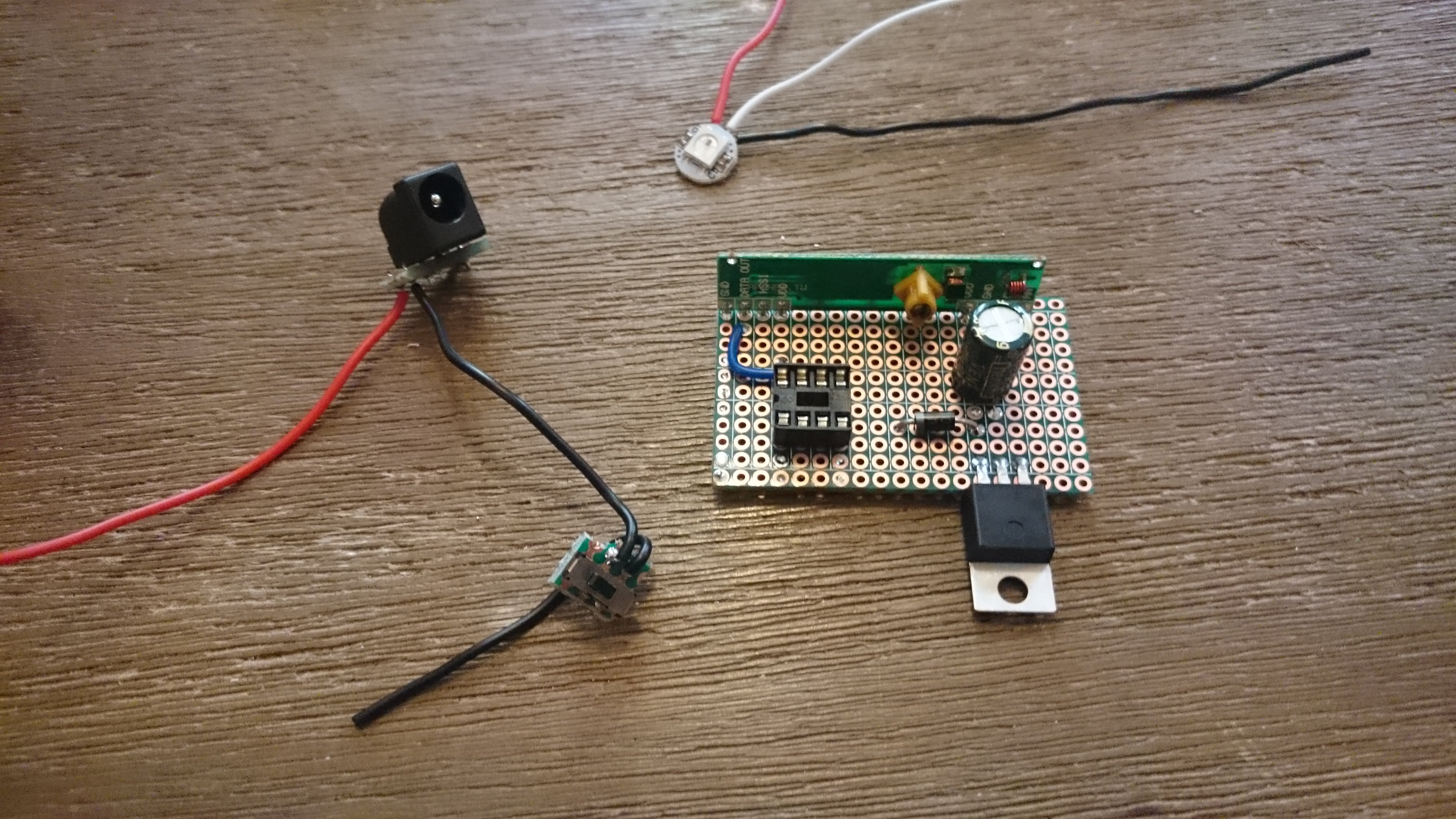
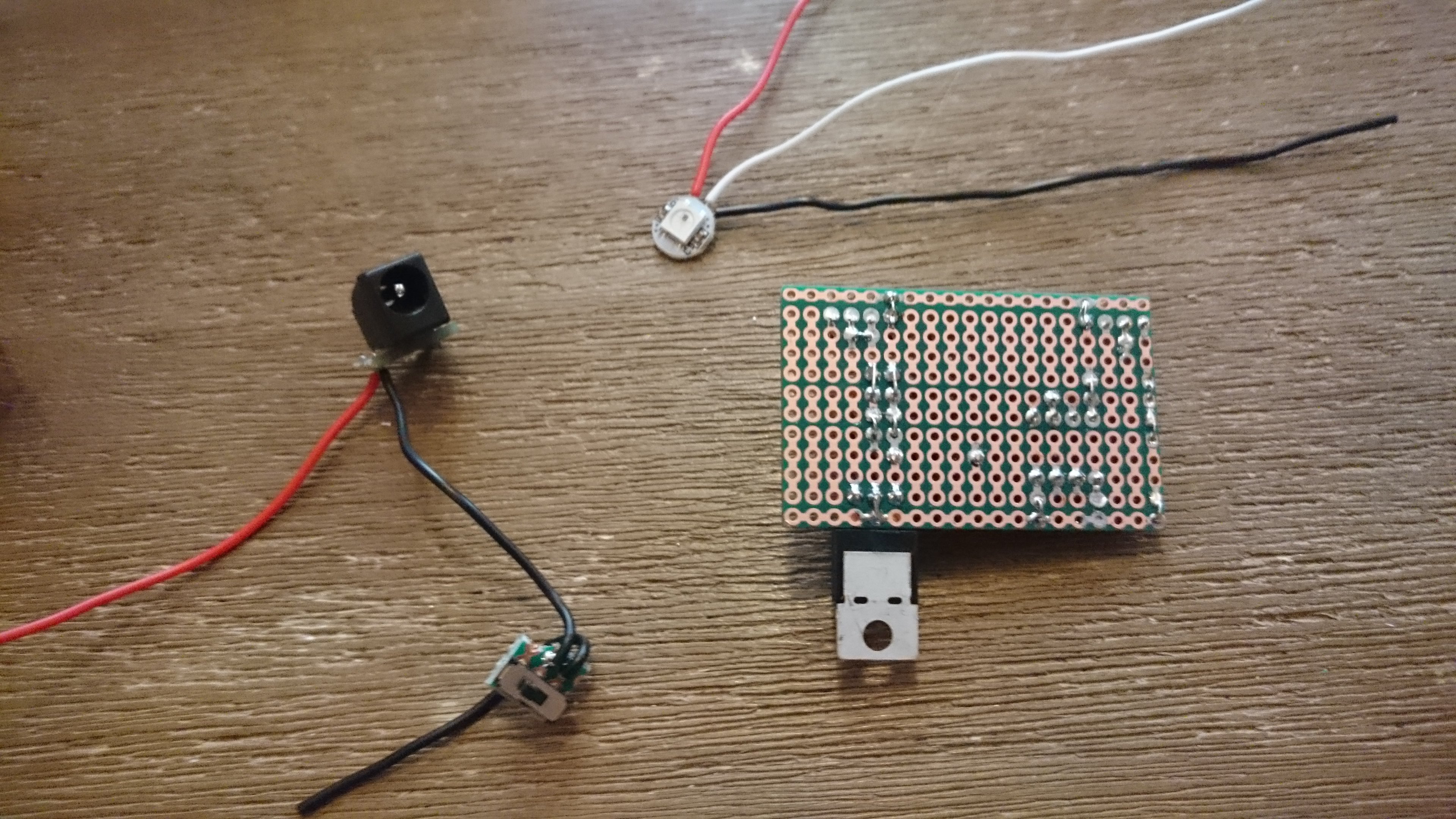
The way you wish to organize your soldering process is up to you. I personally started by soldering the “free” elements (the ON/OFF switch, the IR sensor and the battery holder) to a small piece of PCB along with their connection wires. Then I moved on to the main PCB, starting by the MCU socket and the RF emitter link. I soldered the passive components, the wires and the antenna. Finally I connected the switch and the sensor to the main PCB.
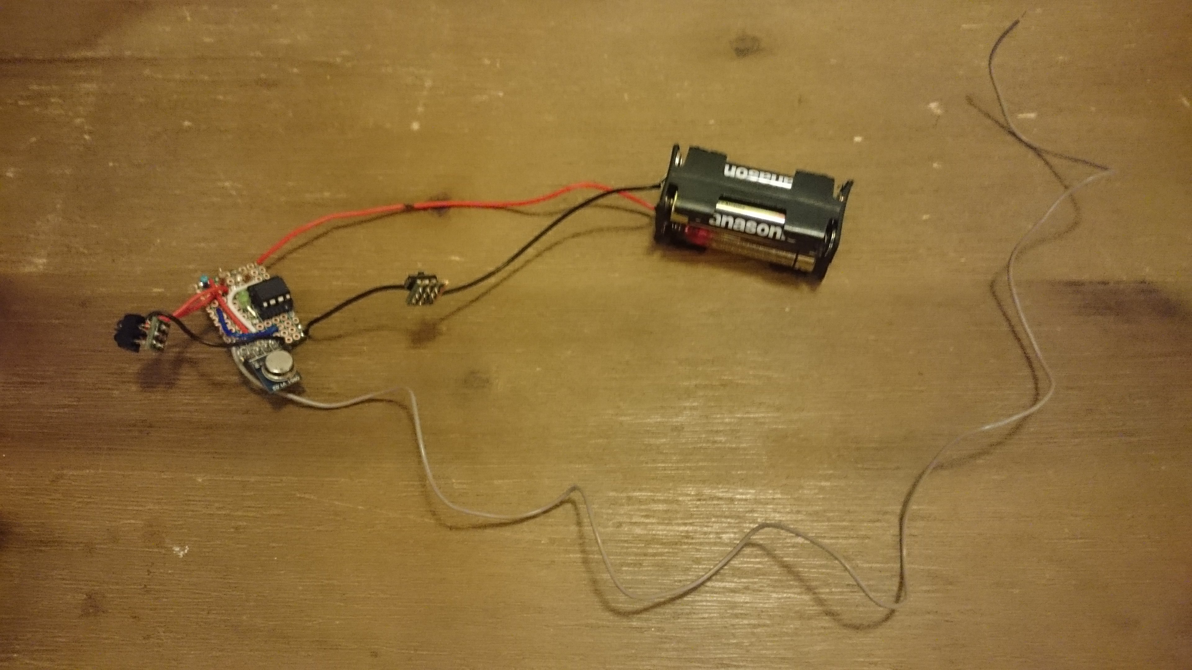
Assembly
Time to put everything together.
First secure the IR sensor and the switch in the slots we made for them in the enclosure. You can use a little hot glue in order to do so.
Then manage to fit the battery holder and the main PCB in the enclosure.
Finally coil the antenna and find some room for it. If you are experiencing difficulties with the range of your devices, you can try to let it hang out of the enclosure. In that case I wanted to emitter device to be as discrete as possible which is why I stuck the antenna inside.
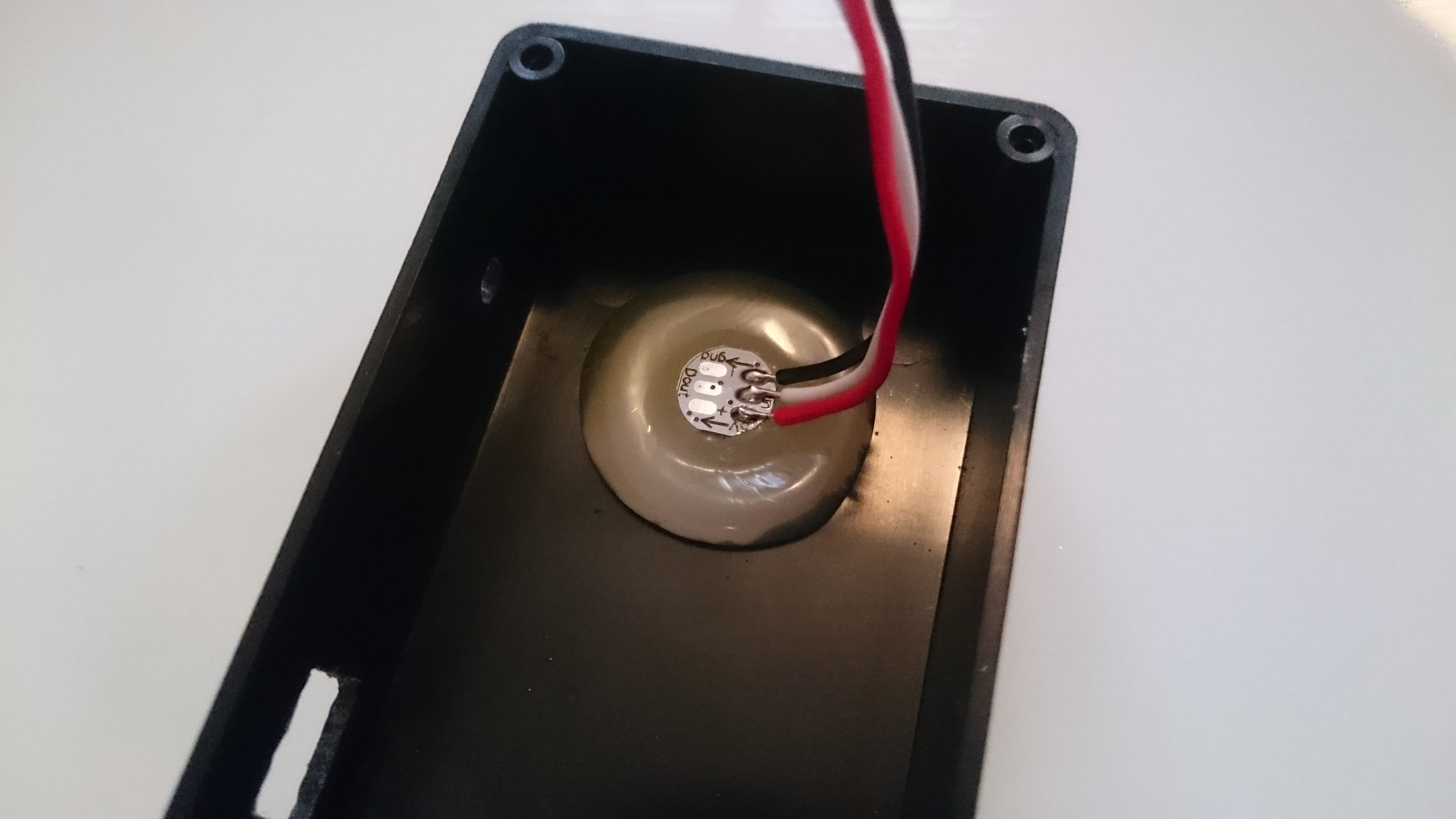
Our first device is ready to be deployed. Let’s review one more time how it will detect if the door is locked or unlocked.
The device is placed so that the IR sensor faces the lock’s knob. A piece of black tape is applied to the knob so that when it is locked, the tape faces the sensor changing the reflectivity of the knob. Inversely when the door is unlocked, the untaped part of the knob faces the sensor.
How does it translates in terms of readings from the analog pin of the emitter ? When the door is locked, the sensor faces a black surface thus the phototransistor receives next to no light. Its resistance is high: the analog reading is high too (close to 1023). When the door is unlocked, the untaped part of the knob reflects a certain amount of light from the IR LED of the sensor back to it. The phototransistor’s resistance is lowered: the value read from the analog pin drops.
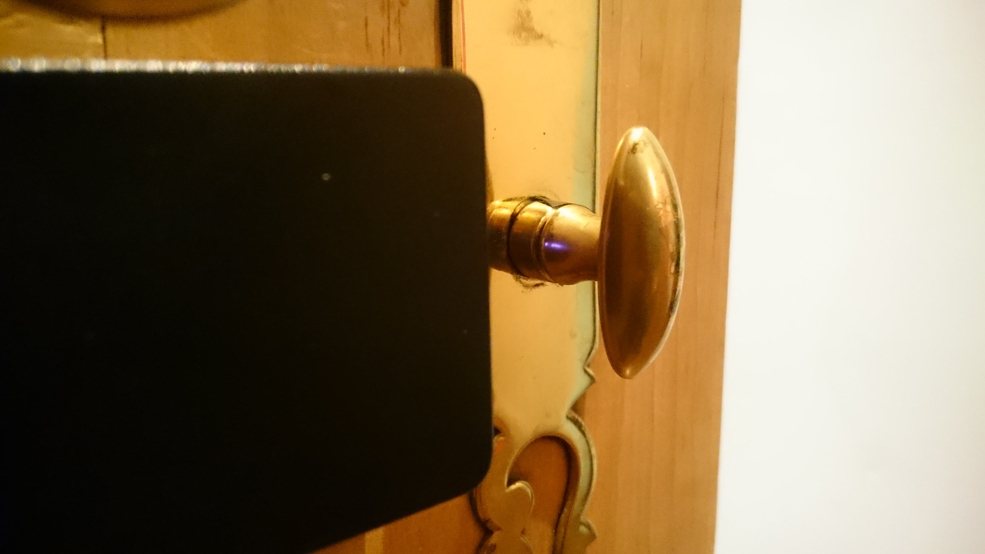
The picture on the right allows you to actually see the beam of IR light being reflected by the knob so it’s easy to pick up the concept.
Receiver device
As I mentioned in the last part, we have one thing to do before permanently soldering the RF receiver. Connect it to the Uno and upload the receiver test code in order to print the values received from the emitter to the Serial console.
In the receiver final script, you need to set two values: closedReflectivity and openReflectivity. They correspond to the value returned by the IR sensor when the door is either locked or unlocked. These values are conditioned by several factors (the normal reflectivity of you knob, the distance between the sensor and the knob etc.) so you need to test your specific set-up and set the values accordingly.
When you are satisfied with your adjustments, you can move on to the next part.
Soldering the circuit
Nothing new here. We solder the “free” components as well as the main perfboard. One difference though: don’t solder the external components to the main PCB just yet as we need to do some additional work on the enclosure.
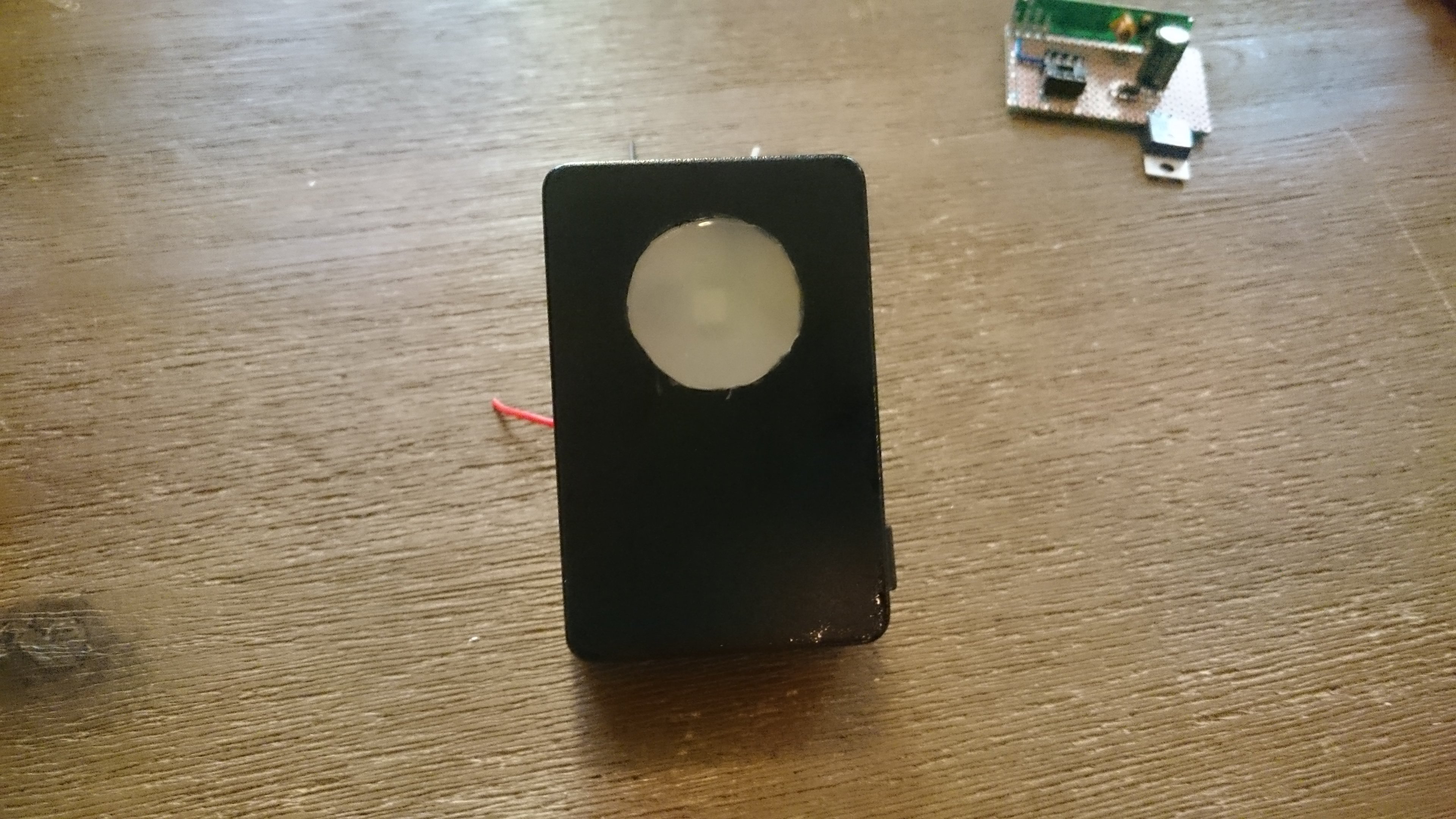
Making the light diffuser
You have experienced first hand that the light of the neopixel is way too bright to be used as is. We can dim it in the code but in that case it won’t be visible for afar which is not good either.
A cheap solution is to use hot glue as a light diffuser. As a semi-opaque and easily manipulable plastic, it makes a good candidate for solving our problem.
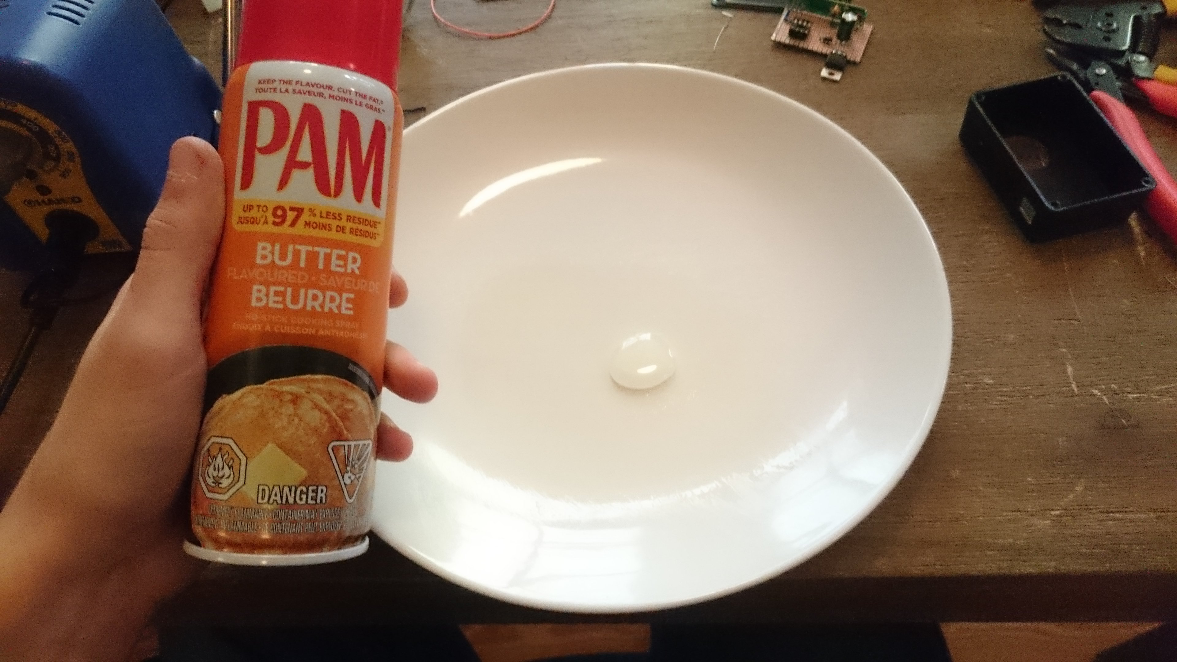
This is when the oil spray comes in handy: see the hot glue is, after all, glue (Duh!). So if you try to melt hot glue on pretty much any surface it will obviously stick to it and you will have much difficulties to separate it when it cooled down.
Spraying oil on the surface that will come in contact with the glue can avoid that. Don’t make the mistake I made: don’t buy butter-flavored oil or you will stink up your workshop (unless you plan on eating your light diffuser afterward)!
The idea is the following:
- use a ceramic plate or a relatively default-free surface, spray it with oil,
- place your enclosure, inside facing you,
- as quickly and smoothly as possible, apply a first layer of hot glue on the light diffuser hole made in the enclosure (you want to pour the glue quickly because it will give a more homogeneous result),
- after around 1/2 minute(s), place the neopixel in the center and apply a soft pressure so that it sticks to the glue,
- wait 2 more minutes and add a little dot of glue on the back of the neopixel (this is so that the PCB traces are properly isolated since things will get pretty stacked in there later on,
- wait again for a few minutes and carefully separate the enclosure from the plate (if the glue is still a bit soft, continue waiting until it is really solid).

I encourage you to make tests beforehand so that you find the best amount of oil to use, how thick to make the diffuser, how much time to wait etc.
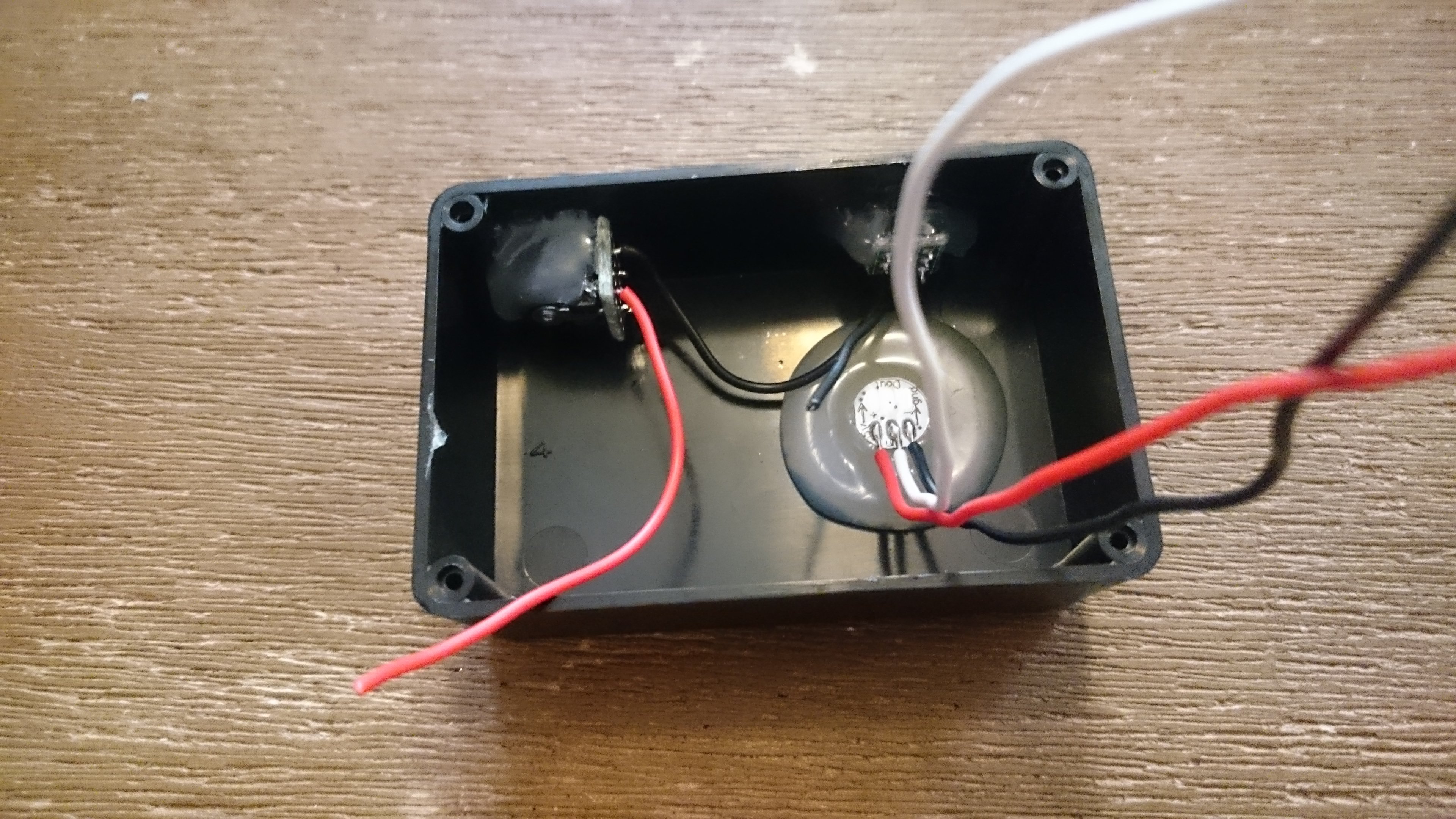
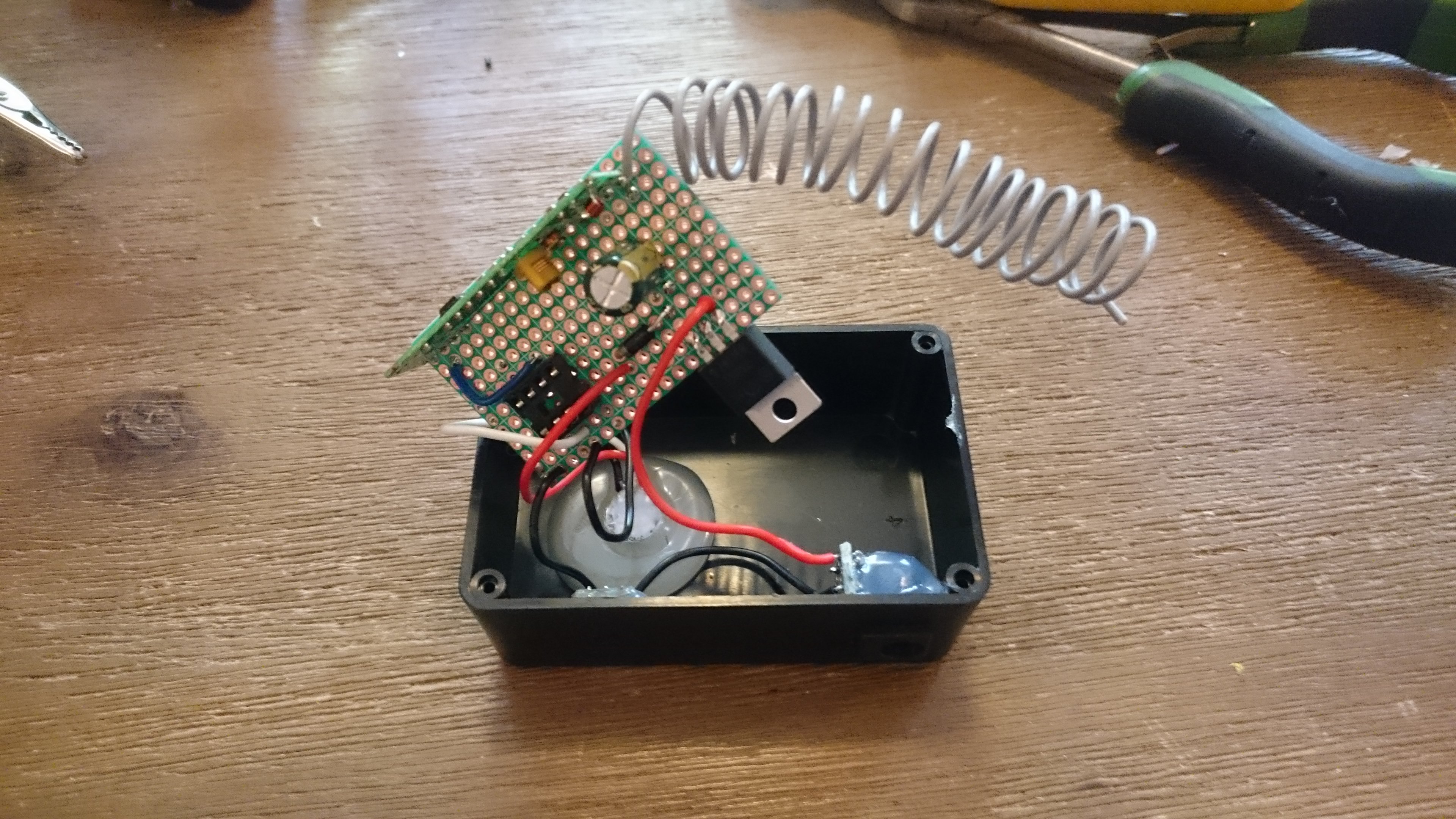
Assembly
Let’s wrap this up!
Assemble the power jack and the switch with the enclosure using a bit of hot glue.
Then solder the connections to the main PCB and coil the wire – or not: once again you may have to leave it hanging out of the enclosure depending on the range you are trying to achieve.
Et voilà! You’re all set, time to put your devices to good use and to avoid your co-workers unnecessary bathroom trips!
Sources
-
Similar projects
- Occupus: Bathroom Occupancy Remote Awareness Technology
- Ocupado: An internet connected restroom occupancy detector
- Loftwork Women’s toilet sensor project
-
Flashing the ATtiny
- Tiny AVR Programmer hookup guide from Sparkfun.
- How to program ATtiny85 with Arduino Uno.
- Programming ATtiny with Arduino 1.6
-
RF communications
- RF 315/433Mhz Transmitter-receiver Module and Arduino
- KLP/KLPA Module Walkthrough
- Sending wireless data from one ATtiny85 to another
-
Manchester library
- Arduino Manchester library website
- Arduino Manchester library github
- Setting up Arduino IDE 1.0 and 1.6 for ATtiny and Manchester library
- Manchester library won’t compile for ATtiny85 on stackexchange