Prologue
I recently got involved with an organization called Wearhacks.
WearHacks is an international non-profit organization headquartered in Montreal, focused on the promotion of innovation and entrepreneurship in Wearable Technology and Internet of Things all over the world.
They asked me to make a fun and seasonal project intended to be used at the Los Angeles Hacktoberfest event in order to introduce high schoolers to the world of IoT.
The result is – behold – the Hack-o-lantern.
What we will be making
The idea is to make a jack-o-lantern controlled via twitter. Commands sent to a specific twitter account allow to change the color of the light inside the pumpkin or perform a pre-defined animation such as opening the pumpkin or playing a spooky sound effect.
A range sensor allows to trigger an action sequence if someone gets close to the jack-o-lantern.
Finally a sound sensor can be used to modulate the light according the the surrounding sound level.
Table of contents
- Building the circuit.
- Twitter app registration and setup.
- Communicating with twitter – IoTDataProvider.
- The code.
- Pumpkin carving and assembly.
Components list
- 1x Spark core (or newer version : Particle photon)
- 1x 16 LEDs NeoPixel ring
- 1x 2500mAh lipo battery
- 1x lipo usb charger/booster or similar
- 1x HS-311 servo motor
- 1x HC-SR04 ultrasonic range sensor
- 1x audio sensor breakout
- 3x 470ohms resistors
- 1x S9013 npn transistor
- 1x diode (1N4001)
- 1x 1000uf capacitor
- 1x breadboard
- 1x perfboard
- 4x female headers
- 1x male header(1×3)
- 1x jst connector (depending on your charger module)
- jumper wires
- wires
- soldering equipment
- 1x hinge
- 2x wooden sticks
- glue gun
- Pumpkin!

Building the circuit
Note: the instructions explaining how to upload the code to your device are available here.
Battery set-up


The circuit is powered by a 3.7v 2500mAh lipo battery. However, some of our components need 5v to function correctly (the servo motor, the range sensor and the LEDs).
This is where the battery charger/booster comes in. Addionnally to providing a way to charge the battery through a usb connection, it also transforms
the 3.7 input voltage into a nice 5v that we need.
The core is equipped with a voltage regulator that allows it to be powered through usb which delivers 5v. The voltage regulator is doing the exact inverse of our
battery booster : it steps a 5v voltage down to the 3.3v that the core needs. By connecting the 5v output of our battery booster to the Vin and GND pin,
we use the same voltage regulator to provide the appriopriate voltage to the spark.
We also add a decoupling capacitor. Why ? Some of the components that we will be using sometimes experience spikes of current consumption (example: when the LEDs are turned on at full brightness, they can briefly sink in a lot of current).
Microcontrollers don’t like variations in their input voltage. It tends to provoke unwanted resets and other instabilities.
This is where the decoupling capacitor comes in handy: it’s basically a very small and temporary battery. As long as the circuit is stable, it will stay charged and basically just sit here.
But if a massive current consumption occurs, the capacitor will release its energy back into the circuit, exactly countering the drop in current.
Think of it like a jar full of water turned upside down inside a bigger bowl also filled with water. If the level of the water in the bowl is higher than the opening of the jar, the water will stay quietly in the jar.
The if the level drops underneath, the water of the jar will fall down back into the bowl, restoring the initial level.
Keep your circuit set-up as it is, we will use it as-is for the next steps.
LED ring
These LEDs are very popular because of their low power consumption as well as their ability to be controled with just one pin. If you don’t understand why this is
such a nice feature, have a look at multiplexing on google and you’ll quickly see that using only 1 pin to control 16 rgb LEDs is awesome.
Start by soldering the wires to your ring. 4 holes are available. You only want to solder Vin, Gnd and Data IN.
Schematics
The circuit is very simple : Vin goes to the 5v power rail, GND to…you guessed it, the GND rail. And finally Data IN is connected to D2 on the spark.
This is the pin that will send the instructions to the LEDs (which color and brightness to use. It’s worth to mention that every LED on the ring can
be controlled individually).
Once again, don’t unplug your components. We will use the LED ring to test the audio sensor’s output in the next step.
Code
Link to the sketch folder.
Upload the code to your device using on of the two methods explained in the Getting started with the Spark Core document. You should see the colors of the rainbowsuccessively appear on your LED ring. Cool isn’t it ?
Sound Sensor
A sound sensor works by detecting differences in air pressure and converting it into an electrical signal, much like your ear does! The key element of the mechanism is a piezzoelectric device. Piezzoelectric means that it converts a mechanical phenomenon (such as the vibration of the membrane caused by the difference in air pressure) into electricity.
The current generated is so tiny that it needs to be amplified so that we can be fed to an microcontroller’s input pin.
Schematics

The sound sensor is a 2.4->5v device, meaning that it can be fed any voltage that falls in that range. The output will be constrained by this value: if say 3v are fed to the device, the output range will be [0;3v]. To simplify, if the device output equals 0v then ne sound is detected. If it is 3v, the maximal sound level is detected (the sensitivity can be adjusted by tweaking the potentiometer in the back, but the default value will do in our case).
Since our spark core is a 3.3v device, it expects inputs <= 3.3v. Never more (you could -and eventually will- damage your microcontroller). This is why we will connect the sensor to the 3.3~v power line of the spark. You may notice that two 3.3v pins are available. We use this one because it is said to be filtered, meaning that it is especially made to provide a steady and reliable voltage for sensitive measurement devices such as our sound sensor.
The output pin goes to the analog input pin A0. An analog input pin works by measuring the voltage being applyied to it.
It then returns the corresponding value to the microcontroller, mapped between 0 and 4096. 0 corresponds to 0v being applied to the pin, 4096 to 3.3v.
We will use this value to determine the current sound level.
The sound level is then used to light up the LED ring (the louder, the more LEDs will be turned on).
Code
Link to the sketch folder.
Upload the code. When the spark is ready, try to clap near the sound sensor or play some music around it. You should see a nice animation being displayed on your LED ring.
Range Finder
The ultrasonic range finder is a pretty nifty device. It works very much like those radars you see in submarines, or like the system bats use to direct themselves. It sends an ultrasonic wave on one side and wait for it to bounce back on a surface placed in front of the sensor.
The wave is picked up by the other side of the device on its way back. The time it took for the wave to make its round-way trip is passed through a simple formula which gives the corresponding distance between the sensor and the opposing surface.
Schematics


Unlike the sound sensor, the range finder is a strictly 5v device. So start by connecting the Vin pin to the 5v power rail (and as always, GND goes to GND. Don’t plug it the other way around by mistake. You will burn your sensor).
The Trig pin is to be connected to D4 on the spark. This pin is used to control when a sound wave is being sent. The result will come through the Echo pin. But wait, if the sensor outputs a 5v signal and the spark can only accept something <= 3.3v, how can we connect the two ? We have to use a voltage divider. It’s a simple circuit composed of two resistors that will sink part of the current to the GND so that the output voltage is reduced.
Code
Link to the sketch folder.
This time, connect the spark core to your computer with the usb cable provided with the kit. Fire up a Serial console and set the baud rate (the number of bits/s) to 9600. Put your hand in front of the range sensor and variate the distance. You should see the corresponding values being printed on your console.
Servo motor
Unlike a DC motor that rotates perpetually when powered on, a servo motor works by receiving an angle option, and rotating its shaft to the following angle.
Schematics


Use the male header to plug the servo to the breadboard. One side of the header may be a bit short to plug-in correctly, so don’t hesitate to switch it for 3 jumper cables if you want.
Connect the Vin cable to the 5v power rail and the GND to the GND rail. The control line (yellow cable) connects to D1 on the spark.
Did you notice the new component ? It’s a diode. We connect it in parrallel between Vin and the GND, as close as possible to the header. In this configuration, it is called a flyback diode. Let’s come back to the water analogy we used earlier. Forget the bowl and imagine a stream of water.
Sometimes when a device like a motor is being powered down (or for the servo, when the rotation has been executed), a reverse spike of voltage is being discharged on the power line. Back to the stream: the reverse spike is like a wave that would travel through the stream in the opposite direction (you can experience this in a delta near the sea when the tide is rising). Well once again, the microcontroller wouldn’t like that. So the diode will block any current stream going in the wrong direction.
Code
Link to the sketch folder.
Upload the code. The servo should start to rotate back and forth on a 180 degrees angle.
Sound Effect module
This is where we put the “hack” in hacking. Playing sound with a microcontroller is not a trivial task, so we will cheat and steal a sound module from
one of those “press me to play a sound” toys. This one was found in a local dollar store.
After extracting the mechanism from the toy comes the fun part : figuring out how to use it with our circuit. In this case, a push-button was triggering the sound routine. A quick test of the PCB traces with a multimeter was enough to understand the mechanism : a pushbutton is used to trigger the sound sequence by closing the circuit. We don’t want to mechanically push a button to trigger the sound, so we have to find a way to trigger it remotly with an electrical signal.
Fortunately, a transistor just does that (and much more but that’s not on topic today): by providing a current to the base (the middle pin),
we open the gate of the transistor, letting current flow from the collector (left pin) to the emitter (right pin).
After a few trial and errors, it appeared that the most reliable way to control the sound module with a transistor was to permanently solder the connection that used to be controlled by the switch, and to let the transistor control the power line of the device. We thus take out the batteries and solder two wires to Vin and GND.


Schematics

What happens is that now the module will play its sound effect as long as it is being powered. We connect the red wire (Vin) to the 5v power rail of the breadboard. This time, the GND is not connected directly but through the transistor. The GND of the device is connected to the collector, the GND of the breadboard to the emitter. The base of the transistor is connected to pin D6 through a 470ohms resistor which is used to protect the transistor from receiving too much current.
If we set D6 to LOW (0v), the gate of the transistor is closed, no current can flow from Vin to GND on our device : it is turned off.
If we set D6 to HIGH (3.3v), the gate of the transistor opens, current can flow and the device is on, playing its sound effect.
Code
Link to the sketch folder.
Upload the code, plug in your usb cable and open the Serial console. Because the sound can get very annoying pretty quickly, the animation will only
start if you send 1 to the console.
Complete circuit
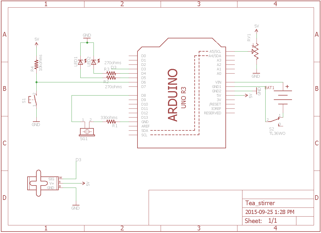

Time to put everything together. The image you see on the left is the circuit schematic, an abstract model of the circuit that allow a trained eye to quickly understand the different elements and their relations. Use it in addition with the right image in order to make the full circuit.

Soldering the circuit
This step is optional.
Start by planning your layout on paper. It’s much easier to erase some pencil writings than to clean an misplaced solder joint!
Use headers so that the elements can be removed temporatly from the circuit and used somewhere else.


Connecting to twitter
Create a new twitter account if you don’t already have one.
Registering a new application on twitter
You then need to create a new application on twitter. Note that you will need to have registered a phone number to your account in order to do that.
By creating a new application, you’re telling twitter that you want to use their services remotly and providing informations about the usage you intend to make.
In return, they will deliver you credentials in order to do so.
Navigate to the following address : http://apps.twitter.com/. Once there, click on Create New App.
You’ll then be asked to provide general informations about your app. What you write in here really doesn’t matter, and you can’t providing an imaginary website address for the Website field.


You will be redirected to your application management page. Click on the Keys and Access Tokens tab.
This is where the credentials you need to write down are. You need 4 pieces of information :
- Consumer Key
- Consumer Secret
- Access Token
- Access Token Secret
The two later are not directly generated. Click on create my access token to create them.


Configuring IoTDataProvider
Note : this website will stay up for the duration of the event, but it might be taken down afterward. You can host your own version following the installation steps of an older tutorial I wrote (IoTDataProvider is directly forked from it so the installations steps are the same). You can find the repository of the website over there.
Fire up a browser at the following address : http://hack.wearhacks.com/.
Start by creating a new account. You’ll be redirected to the clients dashboard.


From there, navigate to the settings page, fill in your twitter credentials and click save changes.


Then, create a new client. Choose a name for your device and add 4 fields using the green + button. Choose the same Api and Method parameters as in the illustration. You will have to choose your own Parameters. In each case, choose the hashtag that will identify the options passed to the tweets, as well as the twitter account that the system should be tracking.
Note that the application will monitor tweets sent to the account, not from it.
When you’re done, hit Create. You will be redirected on the dashboard that now shows your newly created device. Write down the API key somewhere as we will use it in the next step.


You’re all set. Here is an example of a tweet that will be correctly interpreted by the application :
@IoTDH #Mode: auto, #Lights: sound
The system is case sensitive, so make sure that your hastags and keywoards respect that rule.
You can check what will be sent to the core by requesting this url in your browser : http://hack.wearhacks.com/clients/payload?key=YOUR_API_KEY_GOES_HERE.
The response format is : ModeCode, ActionCode, LedsModeCode, R, G, B. If no information is found on twitter for one the the codes, -1 is returned.
The code explained
Link to the sketch folder.
You are encouraged to read through the code. The comments will give you valuable insights on the mechanisms at play. We will nonetheless provide additional details.
Getting data from twitter
The spark core will communicate with twitter through the IoTDataProvider application. In order to authenticate your requests to this service,
you need to modify the sketch by adding the API key we created earlier on IoTDataProvider.
Defining our system’s states
Let’s go through the different states of our pumpkin.
At the highest level, the pumpkin can be either automated on manually controlled. In automatic mode, the pumpkin is keeping track of the distance returned by the range sensor. If it detects a shorter distance than the threshold set in the options at the beggining of the script, it means that somebody is passing by the pumpkin. The animmation is triggered : the pumpkin opens, plays the sound effect for 5 seconds and closes 10 seconds later.
In manual mode, the system waits for a new action code from twitter. When one is received, the corresponding action is executed. By default, the automated mode is actived.
The system that controls the LED is independant from the latter. It means that no mater the mode chosen (manual or auto), the lights can be set to a specific animation.
The animations available are sound-reactive animation, rainbow animation and single color. To enable the single color mode, an hexadecimal color code must be provided in the options from twitter (example: #Color: #D9000).
Here is the list of the keywords corresponding to the different modes and actions, as well as their coded represetation (which is what is received by the core):
General system modes :
- Automated : auto (1)
- Manual : manual (2)
Actions :
- Complete animation (open, sound, close) : animation (1)
- Open pumpkin : open (2)
- Close pumpkin : close (3)
- Trigger sound : play (4)
LEDs modes :
- Sound reactive : sound (1)
- Rainbow animation : rainbow (2)
- Single color : color (3)
A tweet doesn’t need to declare every option. They can be sent individually, in which case a new option will override the last one from the same category.
It takes from 30 seconds to 1 minute until a new tweet is made accessible to twitter’s search function, so don’t be alaramed if a new instruction is not
being executed right away.
Setup() and Loop()
The setup() function is called once when the device boots up. We use it to set up the basic state of our system : we set the pins to the right mode, start the neopixel routine and place the servo in the right angle.
The main loop is the portion of the code being perpetually executed (thus the name). Every 30 seconds, it sends a request to the data provider application in order to check if any new instructions were sent on twitter. Then, two switch structures execute specific routines according to the the instructions retrieved from twitter.
If no instructions can be found, the default routines are executed (the mode is set to automatic and the LEDs show the rainbow animation).
Final assembly
Carving the pumpkin
No instructions needed here. You’re free to let your imagination run wild. One piece of advice though: make sure that the opening of the pumpkin is large enough to let the toy you will use come out when the pumpkin will open.

This pumpkin has been spay painted with an acrylic coating in order to delay the rotting process and to be able to glue the servo motor to the bottom.
The opening mechanism
A hinge for the pumpkin


The head of the pumpkin needs to be able to open and close while staying attached to the body. In order to do that, we use some strong wires that make a loop through both parts of the pumpkin. It’s not perfect, but it works!
Scoop the top as much as possible as the servo won’t be able to lift too much weight.
Making the lever
The mechanism used to open the pumpkin is a very basic lever. The longest segment (let’s call it bigS) is planted into the inside of the top part of the pumpkin.
It must be cut so that the length equals the distance from the bottom of the pumpkin to the back of the top when it is closed.
The small segment (let’s call it smallS) will be attached to the servo. Its length will determine how much the pumpkin opens.
When the servo is in “close” position (angle 0), the lever forms a right angle and its total length = bigS. When the servo is in “open” position,
the lever forms a single segment of length bigS + smallS, thus pushing the top of the pumpkin outward.
Any kind of hinge will do as long as it fits the sticks you chose. If screwing it in isn’t enough to attach it properly, you can use some additional hot glue.


Then cut the sticks at the right dimensions (it will depend on your pumpkin) and screw/glue the small segment to the servo. Make a pointy end to the long segment so that it doesn’t slide off the top part of the pumpkin when in place.


Putting it all together
Time to put everything inside the pumpkin and test the result !
To keep the servo in place, use some strong wire and make a loop that encloses the servo and pierces trough the bottom of the pumpkin.
As for the range sensor, you can place it wherever you like (eye, nose, mouth) as long as its line of sight is not obstructed.
Finally, add a little monster of your choice that will pop out when the pumpkin opens (again, strong wire can be used to attach it to the top).
Congratulations, you made your own interactive pumpkin ! It was not a trivial project so you earned a good tap on the shoulder.
Bonus
Here is the mayor of Los Angeles Eric Garcetti hacking on the project at Hacktoberfest.
